Microincision lens

Active Publication Date: 2012-03-08
JOHNSON & JOHNSON SURGICAL VISION INC
View PDF14 Cites 15 Cited by
  • Summary
  • Abstract
  • Description
  • Claims
  • Application Information

AI Technical Summary

Benefits of technology

[0008]Embodiments of the present invention provide improved lenses that can be inserted through a small incision and unfolded so as to correct at least some aberrations of the eye. Although specific reference is made to intraocular lenses, embodiments as described herein can be used with many forms of vision correction such as contact lenses, spectacles, and implantable lenses such as intraocular lenses corneal inlays. The foldable lens may comprise a first side having a first optical surface disposed thereon, which first optical surface may be have an inner optical surface portion and an outer refractive surface portion. The outer refractive surface portion may comprise a first plurality of convexly curved refractive profile regions having positive optical power to converge light energy with refraction toward a focus on the retina, such that the overall thickness of the lens can be decreased substantially. The convexly curved refractive profile regions of the outer portion may correspond to at least about a quarter of the refractive power of th

Problems solved by technology

Although prior IOLs can be used to replace the degraded crystalline lens and improve vision, at least some prior IOLs can be less than ideal in at least some instances.
The lens inserted through the incision can cause minor distortion of the cornea that may affect patient vision in some instances.
Also, the eye may have chromatic aberration and monochromatic aberration prior to incision, and at least some prior foldable IOLs may not be not well suited to correct chromatic aberration or monochromatic aberration in at least some instances.
Although diffractive lenses and Fresnel lenses have been used with prior IOLs, these lenses can produce p

Method used


Image

  • Microincision lens
  • Microincision lens
  • Microincision lens

Examples


example 1

Optical Surface Parameters for the First Side 110 and Second Side 120

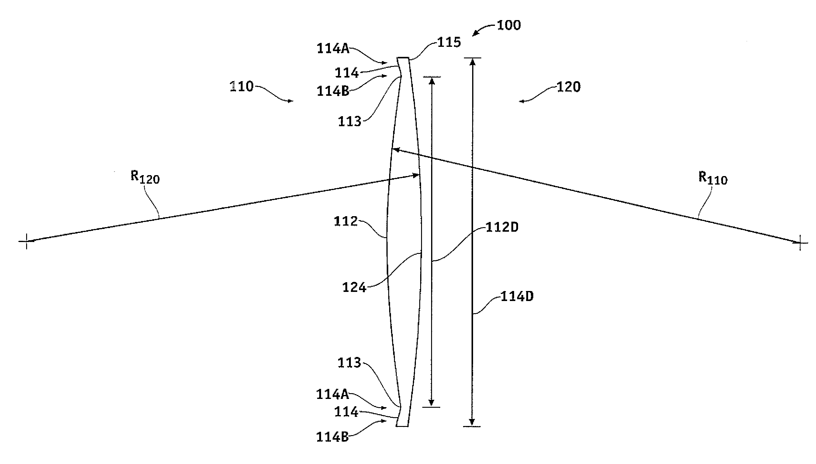
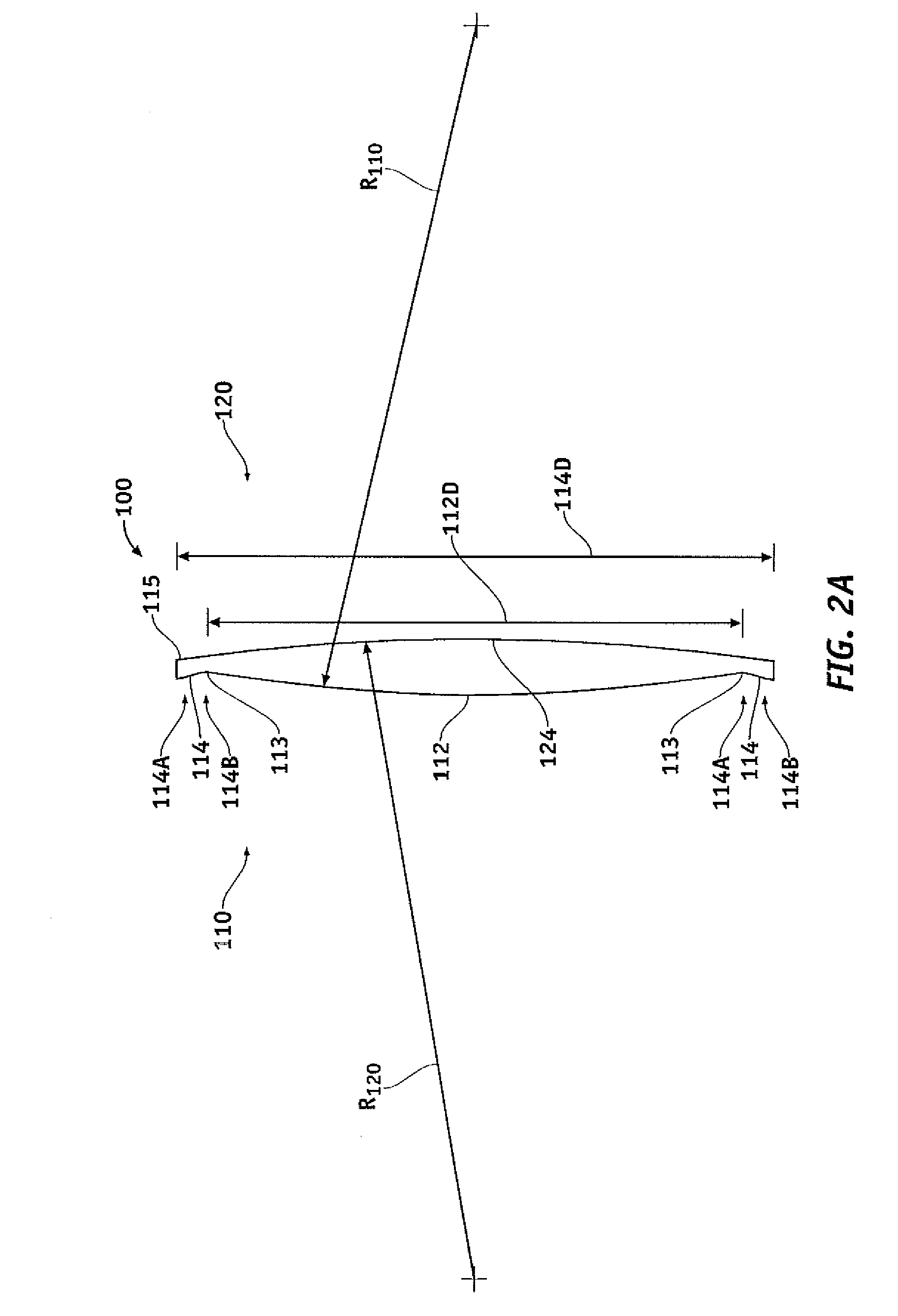
[0058]Tables 1A to 1E show optical surface parameters of the first side 110 and the second side 120 in accordance with embodiments.

[0059]Table 1A shows optical surface parameters of the first side and the second side. The optical power of the lens can be determined with the Thin Lens Equation

D=(n−1) / R

where D is the dioptric power, n is index of refraction and R is the radius of curvature. For an example 20D biconvex foldable lens 100, the radius of curvature R110 of the first side may comprise about 13.4 mm, and the radius of curvature 120 of the second side may comprise about 13.4 mm, and the center thickness about 0.49 mm. The corresponding radius of curvature of the aqueous humor in contact with the foldable lens can be set to −13.4 mm, for example, in accordance with the aqueous humor liquid of the eye in contact with the lens. Alternatively, the first side may comprise an optical power of about 20 D and the s...


PUM


Abstract

A foldable lens comprises an outer refractive surface portion comprising a first plurality of convexly curved refractive profile regions having positive optical power to converge light energy with refraction toward a focus on the retina. The convexly curved refractive profile regions of the outer region may correspond to at least about a quarter of the refractive power of the lens, such that the lens thickness is decreased substantially and the folded lens can fit through a small incision. The outer refractive surface portion focuses light with refraction, in focus images viewed through the outer portion of the lens can appear sharp to the patient. The outer refractive surface portion also comprises a second plurality of concavely curved refractive profile regions having negative optical power disposed between the first plurality, so as to diverge the light energy substantially away from the focus on the retina, such that visual artifacts are inhibited.

Description

BACKGROUND OF THE INVENTION[0001]Embodiments of the present invention relate to vision correction, and in particular to ophthalmic lenses such as contact lenses, spectacles, intraocular lens, or corneal onlays, for example.[0002]People like to see, and the eye is critical for vision. Vision can include distance vision for viewing distant objects and near vision for viewing near objects. Examples of distant objects can include stars and street signs. Examples of near objects can include printed text of a book or a computer screen, for example. Useful vision can also include central vision and peripheral vision. Central vision can be important for viewing objects with high visual acuity, such as reading signs at night. Peripheral vision can be important for detecting peripheral objects, such as speeding and potentially harmful object coming into the field of view such as a speeding car or a projectile, and the human eye has a wide field of view to sense such objects.[0003]In at least ...

Claims


Application Information

Patent Timeline
IPC IPC(8): A61F2/16A61F9/013
CPCA61F2/1656A61F2/1654A61F2/1637A61F2250/0036A61F2002/169053A61F2/1613
Inventor ZHAO, HUAWEI
Owner JOHNSON & JOHNSON SURGICAL VISION INC
Why Eureka
Try Eureka