Hot gas temperature measurement in gas turbine using tunable diode laser

a diode laser and hot gas technology, applied in the direction of optical radiation measurement, instruments, spectrophotometry/monochromators, etc., can solve the problems of high pressure, high temperature of combustion gas in gas turbines, difficult to accurately determine combustion gas temperature, etc., and achieve accurate measurement of firing temperature

Active Publication Date: 2012-03-15
GENERAL ELECTRIC CO
View PDF16 Cites 6 Cited by
  • Summary
  • Abstract
  • Description
  • Claims
  • Application Information

AI Technical Summary

Benefits of technology

[0006]A system and method for accurately measuring the firing temperature or other hot gas temperatures in a gas turbine has been developed. A tunable diode laser directs a laser beam through the combustion gases flowing through a gas turbine. Radiation sensors measure the radiation absorption occurring at wavelengths corresponding to a pair of water vapor overtone transitions in the near-infrared wavelength band. The temperature of the combustion gases is calculated based on a ratio of the measured absorptions at these two wavelengths. The pair of wavelengths are relatively isolated and have no neighboring strong lines of absorption at nearby wavelengths. The isolation and lack of neighboring lines of absorption strength avoids the merging of neighboring strong lines of absorption strength that occurs at the high pressures in a gas turbine.

Problems solved by technology

Combustion gas temperature in a gas turbine is difficult to determine accurately.
The combustion gas is extremely hot, corrosive, turbulent and at a high pressure.

Method used


Image

  • Hot gas temperature measurement in gas turbine using tunable diode laser
  • Hot gas temperature measurement in gas turbine using tunable diode laser
  • Hot gas temperature measurement in gas turbine using tunable diode laser

Examples


Embodiment Construction

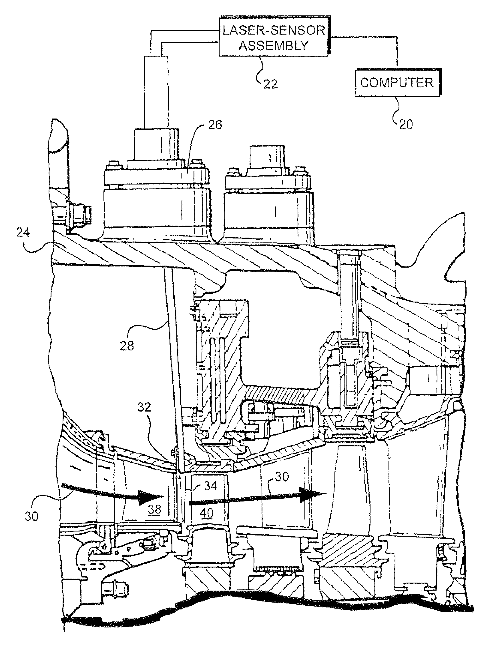
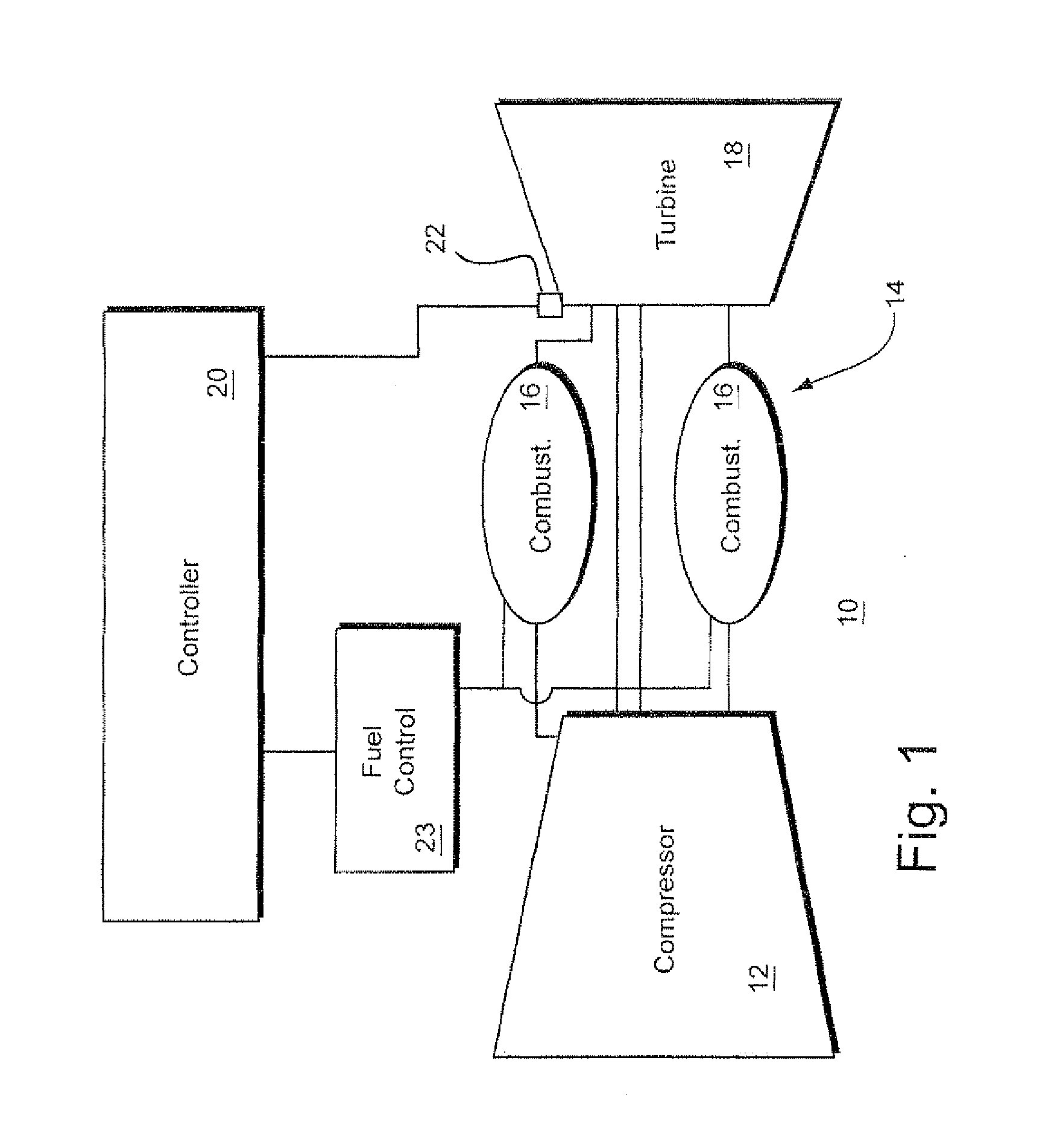
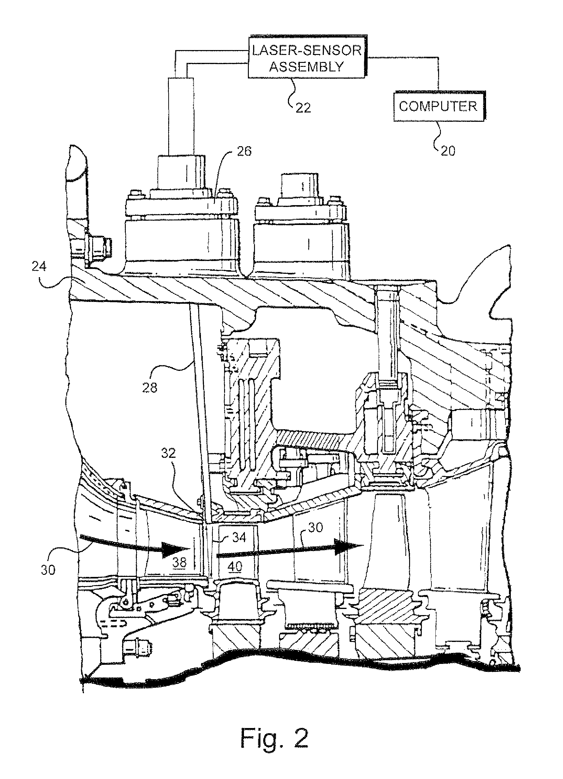
[0016]FIG. 1 is a schematic diagram of an industrial gas turbine engine 10 having a compressor 12, combustor 14 with combustion cans 16 and a turbine 18. Air enters the axial compressor 12 which pressurizes and discharges the air to an annular array of combustion cans 16 that form the combustor. The air and fuel mixture are ignited in the combustion cans and hot gases formed by the combustion flow into the turbine 18. The hot combustion gases 15 enter the turbine 16 and flow over an annular array of first stage stator blades and an annular array of first stage turbine buckets. The flow of hot combustion gas flow over the rows of annular arrays turbine buckets, rotate the turbine buckets and associated shaft which is also connected to the compressor. The rotation of the compressor by the turbine causes the compressor to pressurize the air for the combustor.

[0017]The temperature of the hot combustion gases entering the turbine is conventionally referred to as the firing temperature (T...


PUM


Abstract

A combustion gas measurement apparatus mounted in a gas turbine including: a tunable laser generating a radiation beam passing through a combustion gas path; a controller tuning the laser to emit radiation having at least a first selected wavelength and a second selected wavelength which both correspond to temperature-dependent transitions of a combustion species of the gas, wherein the first selected wavelength and the second selected wavelength are not near absorption peaks of neighboring wavelengths; a detector sensing the radiation beam passing through the combustion gas and generating an absorption signal indicative of an absorption of the beam by the combustion gas at each of the first wavelength and the second wavelength, and a processor executing a program stored on a non-transitory storage medium determining a combustion gas temperature based on a ratio of the adoption signals for the first wavelength and the second wavelength.

Description

BACKGROUND OF THE INVENTION[0001]The invention relates to determining hot gas temperatures using a tunable laser, and particularly to determining high pressure, combustion gas temperatures in a gas turbine.[0002]Combustion gas temperature in a gas turbine is difficult to determine accurately. The combustion gas is extremely hot, corrosive, turbulent and at a high pressure. Combustion gas temperature, e.g., turbine firing temperature (Tfire), is conventionally estimated based on factors such as exhaust gas temperature and compressor discharge gas pressure. This estimation of combustion gas temperature has a certain level of uncertainty. To compensate for this uncertainty, the combustion gas temperature is set at a temperature lower than would be needed if the combustion temperature where known to a greater uncertainty.[0003]Combustion gas temperature affects the power output of a gas turbine. Power increases as the combustion gas temperature is increased. For example, increasing comb...

Claims


Application Information

Patent Timeline
Patent Type & Authority Applications(United States)
IPC IPC(8): F02C7/20H01S3/10
CPCG01J3/108G01J3/427G01K2013/024G01K13/02G01K11/12G01K13/024
Inventor BADAMI, VIVEK VENUGOPALHOYTE, SCOTT MORDINMITRA, CHAYANBANERJEE, AYAN
Owner GENERAL ELECTRIC CO
Why Eureka
Try Eureka