
Method And System For Magnetic Resonance Imaging, And Use Thereof

Active Publication Date: 2012-03-15
RANDOM WALK IMAGING AB
View PDF2 Cites 8 Cited by
  • Summary
  • Abstract
  • Description
  • Claims
  • Application Information

AI Technical Summary

Benefits of technology

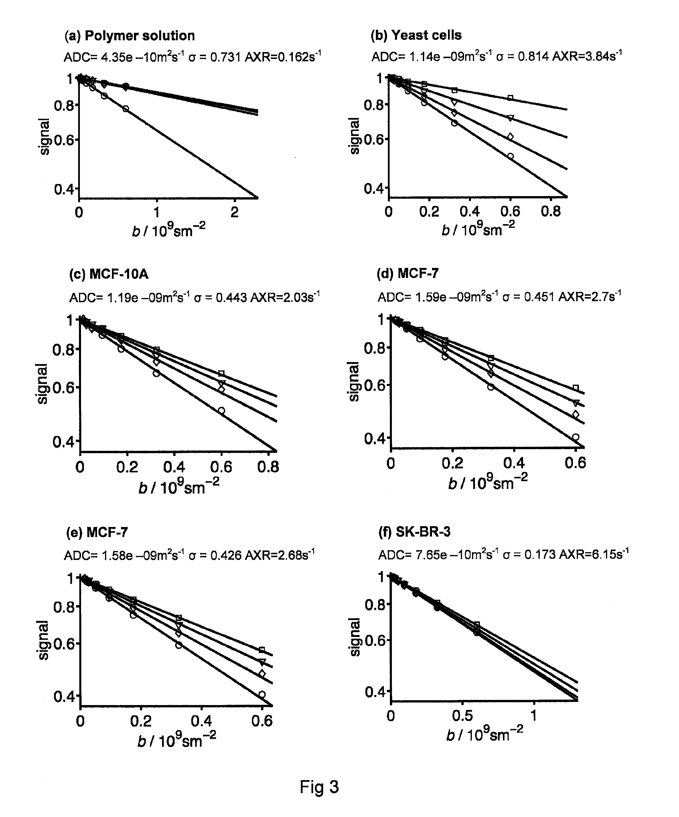
[0015]In comparison to previous protocol described in WO2008 / 147326, less signal attenuation is needed to get the information about exchange. For the case of diffusion weighting, less signal attenuation means that correspondingly lower values of the diffusion weighting parameter b and the gradient amplitude G can be used. The protocol can thus be implemented on any clinical MRI scanner and not only the most modern ones with very high maximum gradient strength (>40 mT / m). Less signal attenuation also means that the signal is less affected by noise.

Problems solved by technology

The analysis is hampered by the weak dependence of the NMR signal on the exchange rate.
However, a serious drawback is the inordinate demands on instrument time for acquiring the large amount of data required for the two-dimensional inverse Laplace analysis, thus making the method impractical for studies of human subjects with limited patience.
This is not only difficult to use in vivo due to the toxicology risks but one could never assure that the tissue and body fluids are unaffected by the introduced marker.
However, there also exist problems with the method and the protocols disclosed in the PCT application WO2008 / 147326 and with Callaghan's protocol.
One such problem is the fact that these protocols are not applicable on all MRI instruments.
Some of the standard MRI scanners used today cannot acquire enough data to allow for e.g. a method according to WO2008 / 147326 to be applied, such as for a global two component fit or ILT analysis.
Another problem with clinical MRI is the in general high noise levels.
Due to the large data acquisition according to WO2008 / 147326, noise may in fact be a large problem.

Method used


Image

  • Method And System For Magnetic Resonance Imaging, And Use Thereof
  • Method And System For Magnetic Resonance Imaging, And Use Thereof
  • Method And System For Magnetic Resonance Imaging, And Use Thereof

Examples


Embodiment Construction

According to the Present Invention

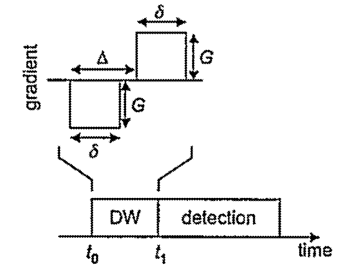
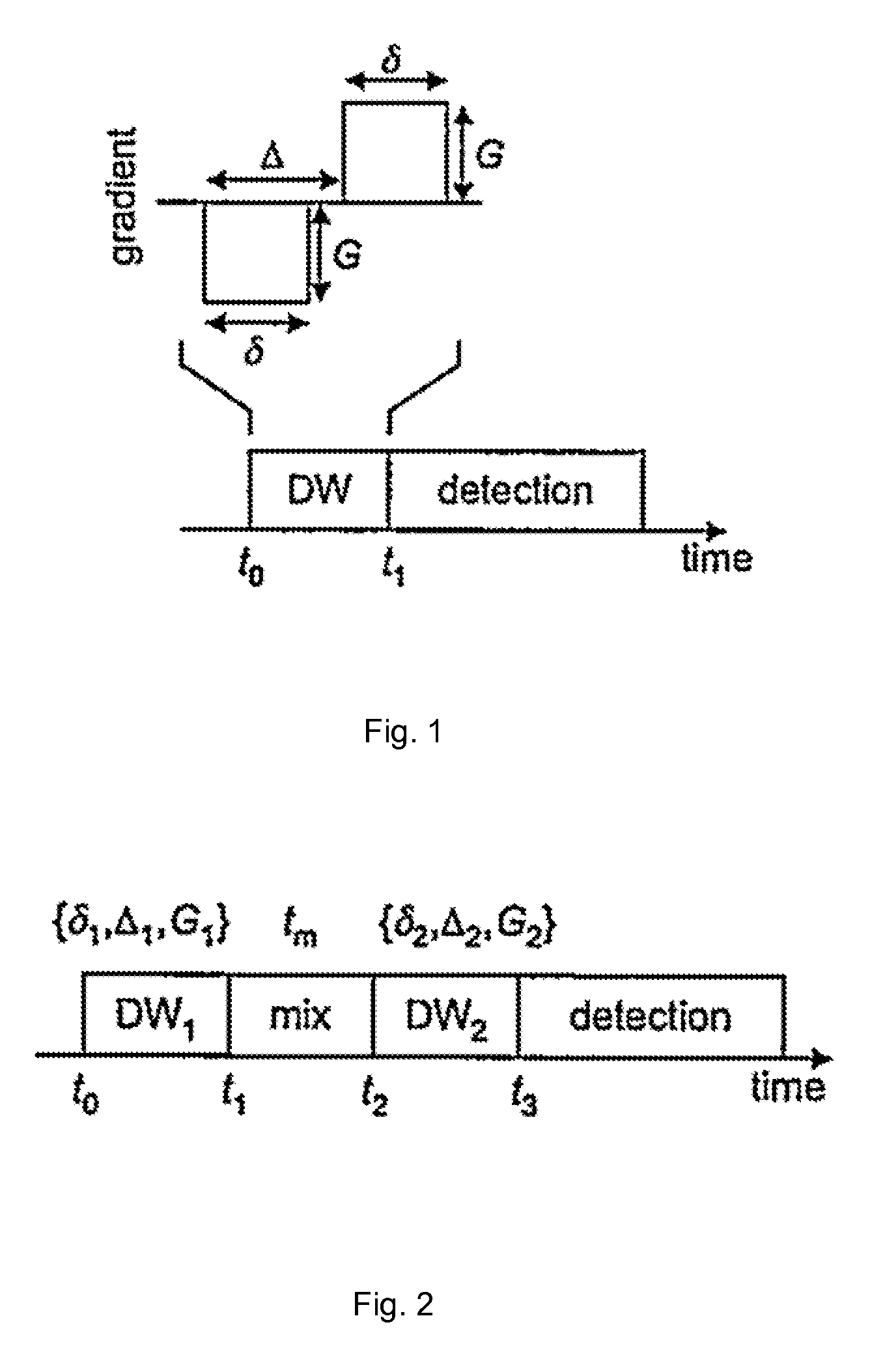
[0051]As may be noticed from the summary of the invention above, the method according to the present invention is directed to encoding, detecting and acquiring the magnetic resonance signal from said object by limitation to initial decay of the signal intensity I. According to the present invention this may be accomplished by use of different types of weighting blocks before and after the mixing block (i.e. the first and second weighting block). Therefore, according to one specific embodiment of the present invention there is provided a method according to the invention,

wherein the first weighting block is a first relaxation weighting block with relaxation weighting τ1 and the second weighting block is a second relaxation block with relaxation weighting τ2, and wherein encoding, detecting and acquiring the magnetic resonance signal from said object is limited to the initial decay of the signal intensity I with increasing τ1 or τ2, to obtain the appa...


PUM


Abstract

The present invention refers to a method for magnetic resonance imaging or nuclear magnetic resonance spectroscopy comprising emitting a radio frequency and gradient pulse sequence towards an object being subjected to a magnetic field, wherein said object comprises a molecule having an atom with a nuclear spin differing from 0, encoding, detecting and acquiring a magnetic resonance signal from said object corresponding to said emitted radio frequency and gradient pulse sequence, wherein the radio frequency and gradient pulse sequence comprises a first weighting block, a mixing block with duration tm and a second weighting block, and wherein encoding, detecting and acquiring the magnetic resonance signal from said object is limited to initial decay of the signal intensity I with increasing strength of at least one of the first weighting block and the second weighting block, wherein the variation of the initial signal decay rate with tm is analysed to obtain the apparent exchange rate AXR.

Description

FIELD OF THE INVENTION[0001]This invention pertains in general to the field of Nuclear Magnetic Resonance and Magnetic Resonance Imaging.BACKGROUND OF THE INVENTION[0002]Diffusion Nuclear Magnetic Resonance (NMR) has been used for over 40 years to determine self-diffusion coefficients, which may be interpreted in terms of aggregate size, permeability of the medium through which the molecules are moving, and binding events occurring between the diffusing species and larger molecules or the porous matrix. The most common diffusion NMR techniques rely on a diffusion encoding block comprising pairs of magnetic field gradient pulses to label the NMR radio frequency signal for displacements occurring during the time between the pulses. Diffusion NMR techniques and methods of analysis are not only applied in vitro but also in the context of medical magnetic resonance imaging (MRI) for the detection of pathological conditions such as ischemic stroke, demyelinization disorder, and tumours. I...

Claims


Application Information

Patent Timeline
IPC IPC(8): G01R33/46G01R33/48
CPCG01R33/56341A61B5/055G01R33/46G01R33/4616G01R33/5608G01R33/3635G01R33/4625G01R33/54G01R33/5602G01R33/56563G01N24/08G01R33/50G01R33/448
Inventor TOPGAARD, DANIEL
Owner RANDOM WALK IMAGING AB
Learn More