Supercharge Your Innovation With Domain-Expert AI Agents!

Thin-oxide current clamp

a current clamp and thin-oxide technology, applied in the field of current clamps, can solve problems such as circuit failur

Active Publication Date: 2012-03-15
TEXAS INSTR INC
View PDF4 Cites 1 Cited by
  • Summary
  • Abstract
  • Description
  • Claims
  • Application Information

AI Technical Summary

Benefits of technology

[0006]An example of thin-oxide current clamp includes a clamp transistor in current-conducting relation between a voltage-sensitive circuit and a common return of a power supply, the clamp transistor responsive to a sense output signal to provide a low-resistance current flow path from the voltage-sensitive circuit to the common return and thereby clamp a voltage in the voltage-sensitive circuit. The thin-oxide current clamp also includes a current source that provides a controlled current and a reference current minor having first and second NMOS transistors with sources connected to the common return, the reference current minor receiving th

Problems solved by technology

Lower voltage and thinner gate oxide are both concomitant with lower power consumption and higher switching speeds.
However, when an inevitable anomalous high voltage spike happens, which can occur due to an impedance mismatch, an inductive coupling with a higher voltage line, or due to the need to support legacy protocols that used thicker gate-oxides and higher voltages, then the thin-oxide gate will breakdown and result in circuit failure.

Method used


Image

  • Thin-oxide current clamp
  • Thin-oxide current clamp
  • Thin-oxide current clamp

Examples


Embodiment Construction

[0011]It should be observed that system components have been represented by conventional symbols in the figures, showing only specific details that are relevant for an understanding of the present disclosure. Further, details that may be readily apparent to person ordinarily skilled in the art may not have been disclosed. In the present disclosure, relational terms such as first and second, and the like, may be used to distinguish one entity from another entity, without necessarily implying any actual relationship or order between such entities.

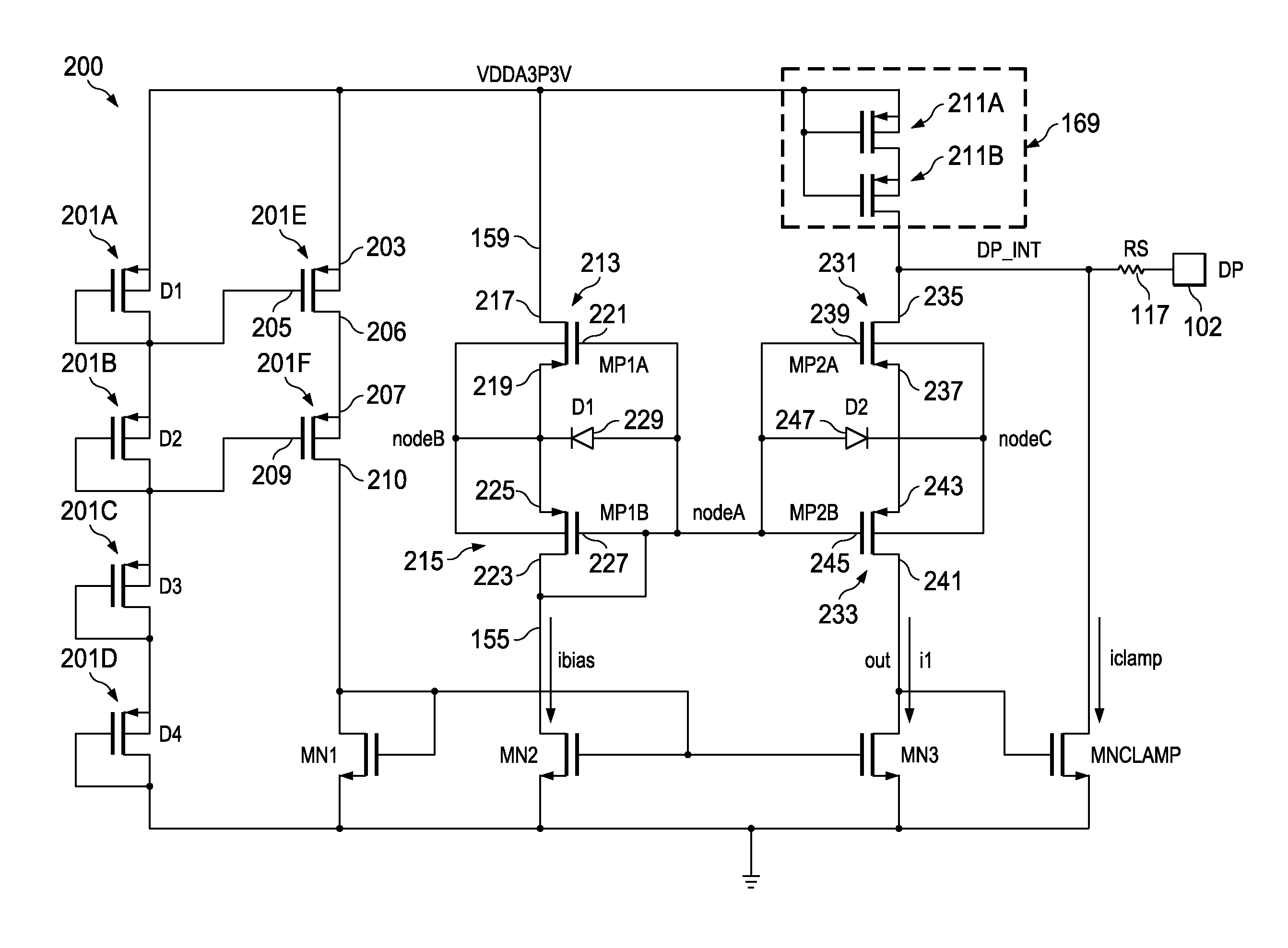
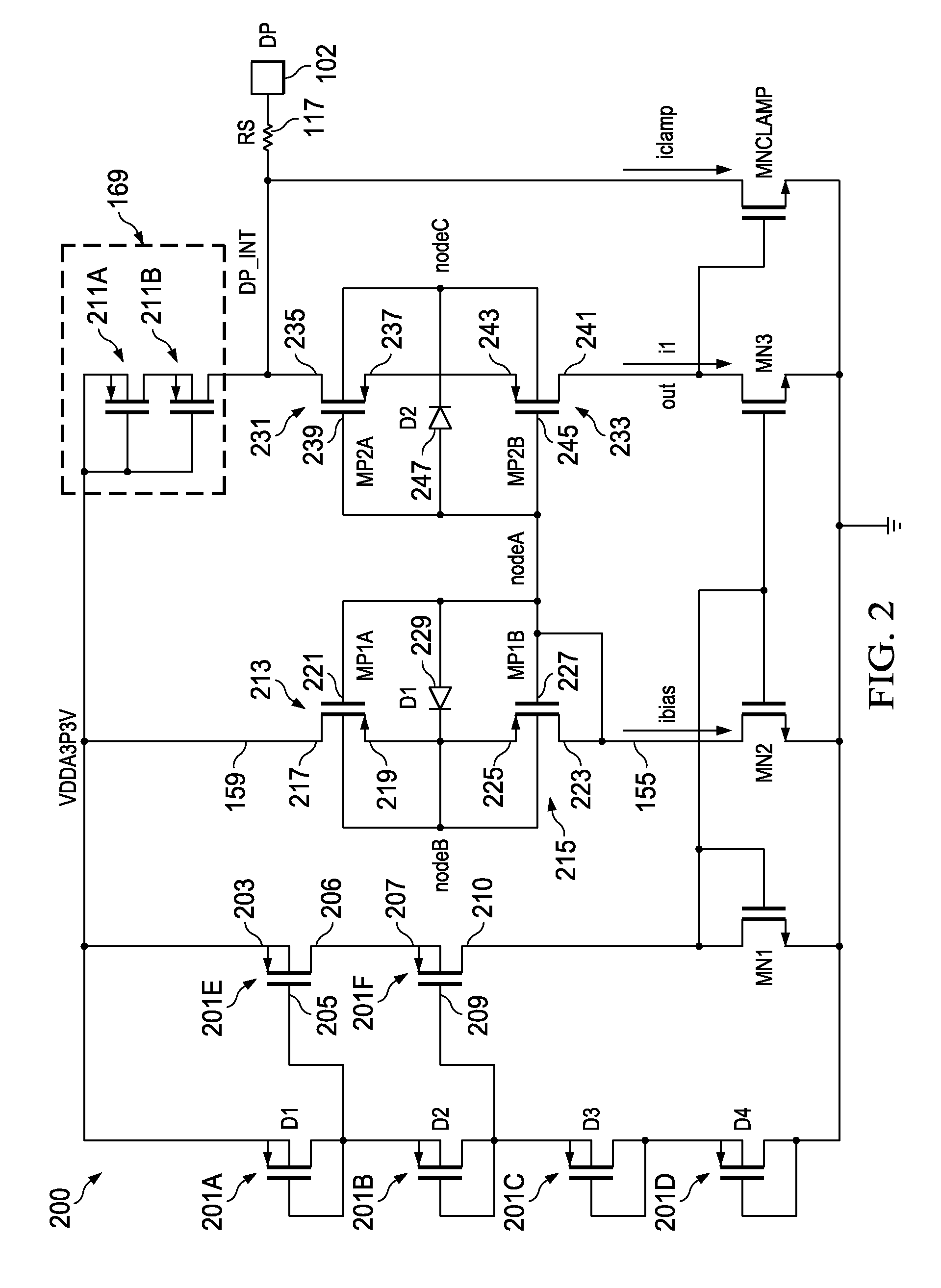
[0012]Various embodiments discussed in this disclosure pertain to current clamps that prevent excessive current drawn due to the anomalous high voltage condition.

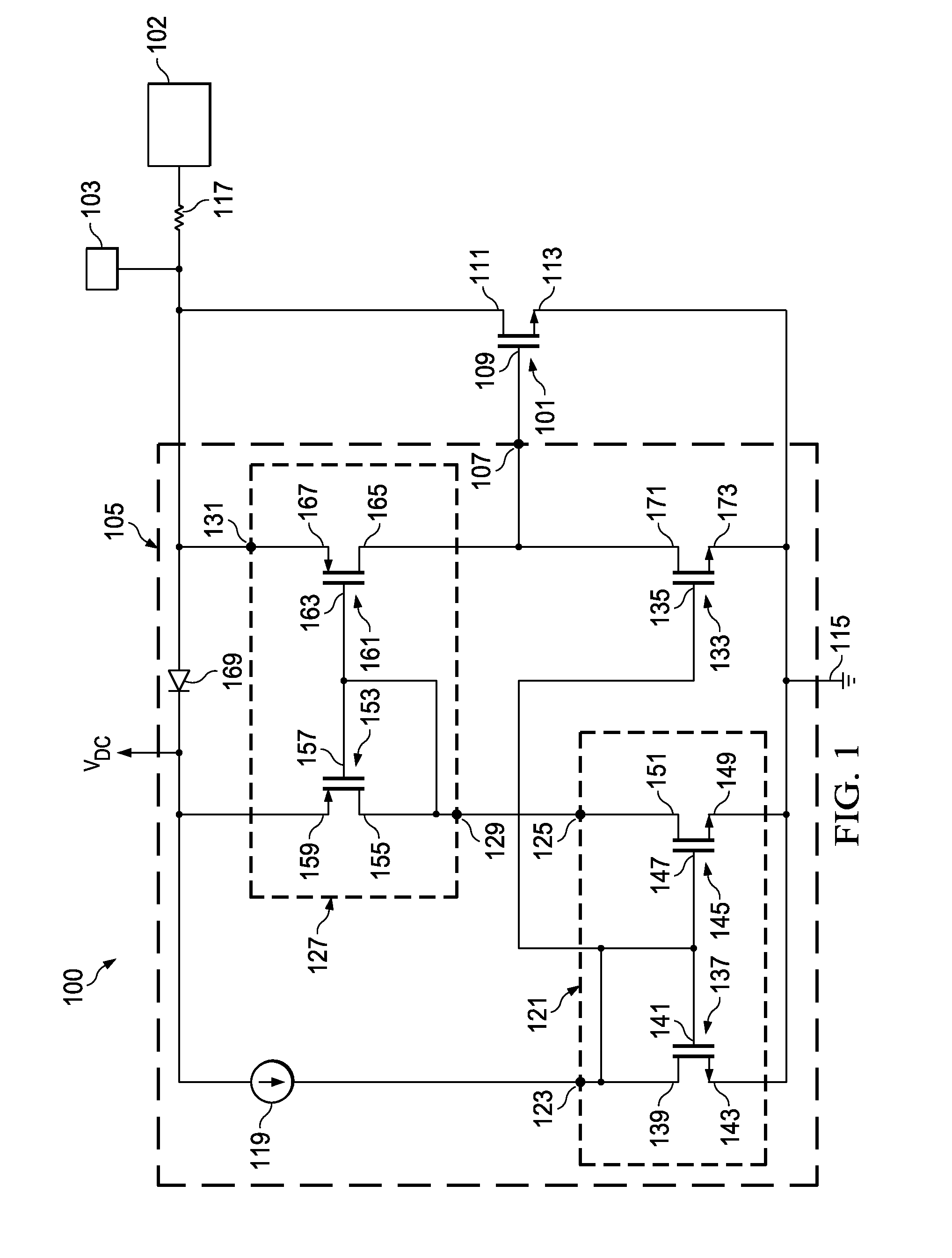
[0013]FIG. 1 is a circuit diagram of a thin-oxide current clamp 100. The thin-oxide current clamp 100 includes a clamp transistor 101 in communication with a voltage-sensitive circuit 103. At the interface between the voltage-sensitive circuit 103 and the current clamp 100 is a pad 1...


PUM


Abstract

A thin-oxide current clamp includes a clamp transistor in current-conducting relation between a voltage-sensitive circuit and a common return of a power supply, the clamp transistor responsive to a sense output signal to provide a low-resistance current flow path from the voltage-sensitive circuit to the common return and thereby clamp a voltage in the voltage-sensitive circuit. The thin-oxide current clamp also includes a current source and a reference current minor, the reference current minor providing a reference current. Further, the thin-oxide current clamp includes a sense current mirror providing a sense current. Further, the thin-oxide current clamp also includes an output transistor that receives the sense current and provides a current flow to a gate of the clamp transistors if the sense current exceeds the reference current.

Description

[0001]This application claims priority from Indian Provisional Application Serial No. 2639 / CHE / 2010 filed on Sep. 9, 2010 entitled “AN OVER VOLTAGE (5V) PROTECTION CIRCUIT IN UDSM TECHNOLOGY WITHOUT ANY 3.3V GATE OXIDE TRANSISTOR FOR USB2.0 APPLICATION”, which is hereby incorporated in its entirety.TECHNICAL FIELD[0002]In general, embodiments of the disclosure relate to current clamps. More particularly, the disclosure relate to over-voltage (5V) protection circuit for USB 2.0 application.BACKGROUND[0003]Currently in electronics circuit design, there is a trend towards miniaturization, specifically, towards the thinning of the oxide layer that forms the insulator between the gate-electrode and the channel in a MOS transistor. As a result of this thinning, the voltages supportable at the gate-electrode, as well as the gate-to-source voltage and the drain-to-source voltage become smaller. Lower voltage and thinner gate oxide are both concomitant with lower power consumption and higher...

Claims


Application Information

Patent Timeline
IPC IPC(8): H02H9/04
CPCH02H9/041
Inventor SETH, SUMANTRAWADEKAR, JAYESH
Owner TEXAS INSTR INC
Features
  • R&D
  • Intellectual Property
  • Life Sciences
  • Materials
  • Tech Scout
  • Unparalleled Data Quality
  • Higher Quality Content
  • 60% Fewer Hallucinations
Learn More