Recombinant factor viii having enhanced stability following mutation at the a1-c2 domain interface

a domain interface and recombinant factor technology, applied in the field of recombinant factor viii having enhanced stability following mutation at the a1c2 domain interface, can solve the problems of significant destabilization of cofactors, increased rate of activity decay, and undesirable mutation types, and achieve the effect of increasing the buried hydrophobic area, reducing the buried hydrophilic area, and enhancing inter-domain binding affinity

Inactive Publication Date: 2012-03-15
UNIVERSITY OF ROCHESTER
View PDF4 Cites 25 Cited by
  • Summary
  • Abstract
  • Description
  • Claims
  • Application Information

AI Technical Summary

Benefits of technology

[0019]The present invention demonstrates that a number of residues at the interface of A1 and C2 domains do not participate in non-covalent bonding, but instead may be destabilizing to factor VIII structure. Replacement of these residues with more hydrophobic residues—with the aim of increasing the buried hydrophobic area and reducing the buried hydrophilic area—was shown in the accompanying Examples to enhance inter-domain binding affinity. Stability parameters were assessed by following the activity of the factor VIII variants. Results from these studies demonstrated that a number of mutations yielded increased stability parameters. These stabilized variants of factor VIII and activated cofactor VIIIa should afford an improved therapeutic for treatment of hemophilia A.
[0020]To explore the role of this region in factor VIII and factor VIIIa stability, a variant containing a disulfide bond between A1 and C2 domains was generated by mutating Arg121 and Leu2302 to Cys (R121C-L2302C) and a second variant was generated by substituting a bulkier hydrophobic group (Ala108Ile) to better occupy a cavity between A1 and C2 domains. Disulfide bonding in the R121C-L2302C variant was >90% efficient as judged by western blots. Binding affinity between the Ala108Ile A1 and A3C1C2

Problems solved by technology

However, it has since been suggested that these types of mutation may not be desirable in a therapeutic factor VIII, because they substantially eliminate means for down-regulation.
This situation could yield a prothromb

Method used


Image

  • Recombinant factor viii having enhanced stability following mutation at the a1-c2 domain interface
  • Recombinant factor viii having enhanced stability following mutation at the a1-c2 domain interface
  • Recombinant factor viii having enhanced stability following mutation at the a1-c2 domain interface

Examples


example 1

Recombinant Expression and Purification of Factor VIII Mutants Possessing Modified A1 and C2 Domain Interactions

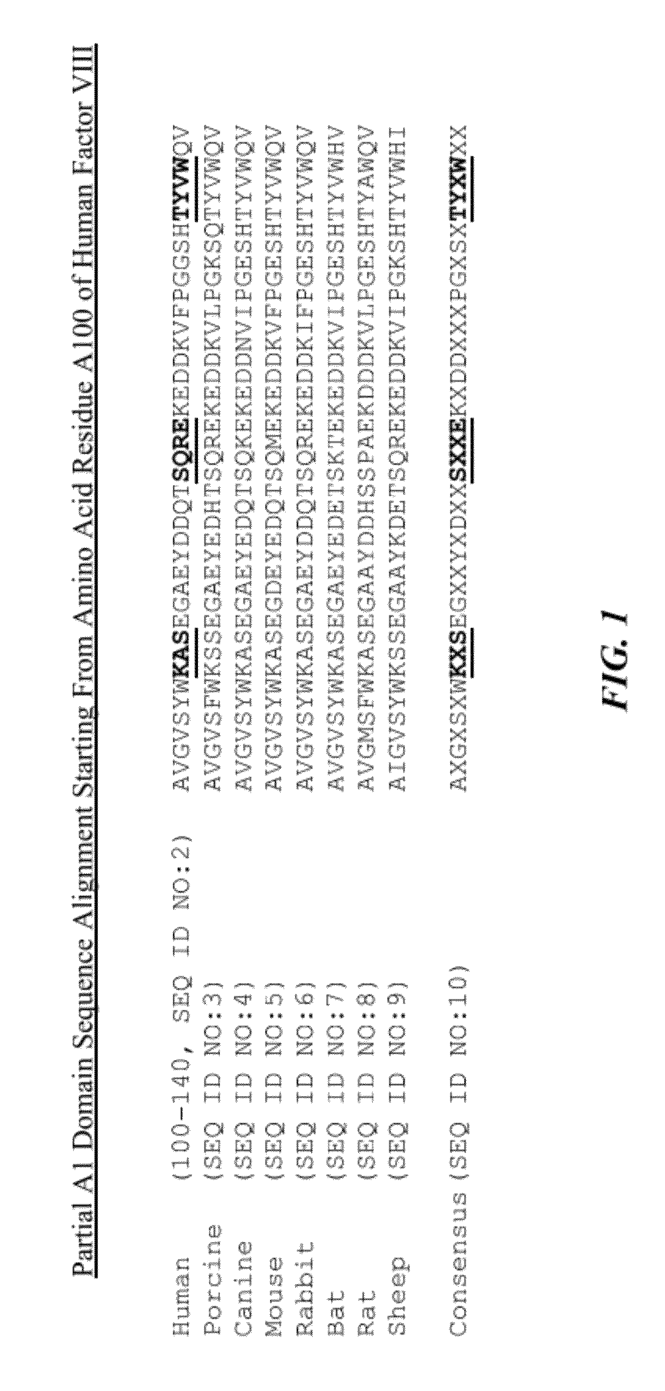
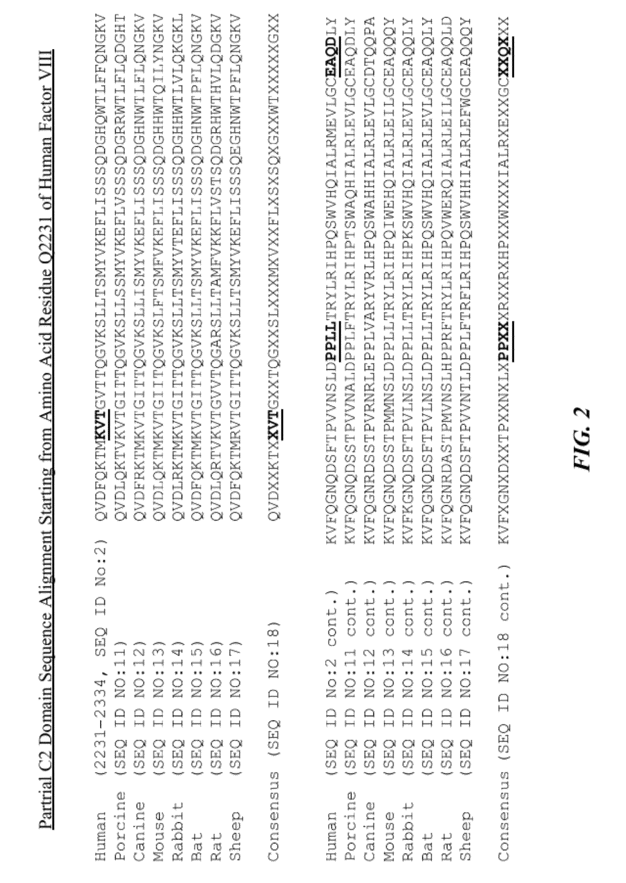
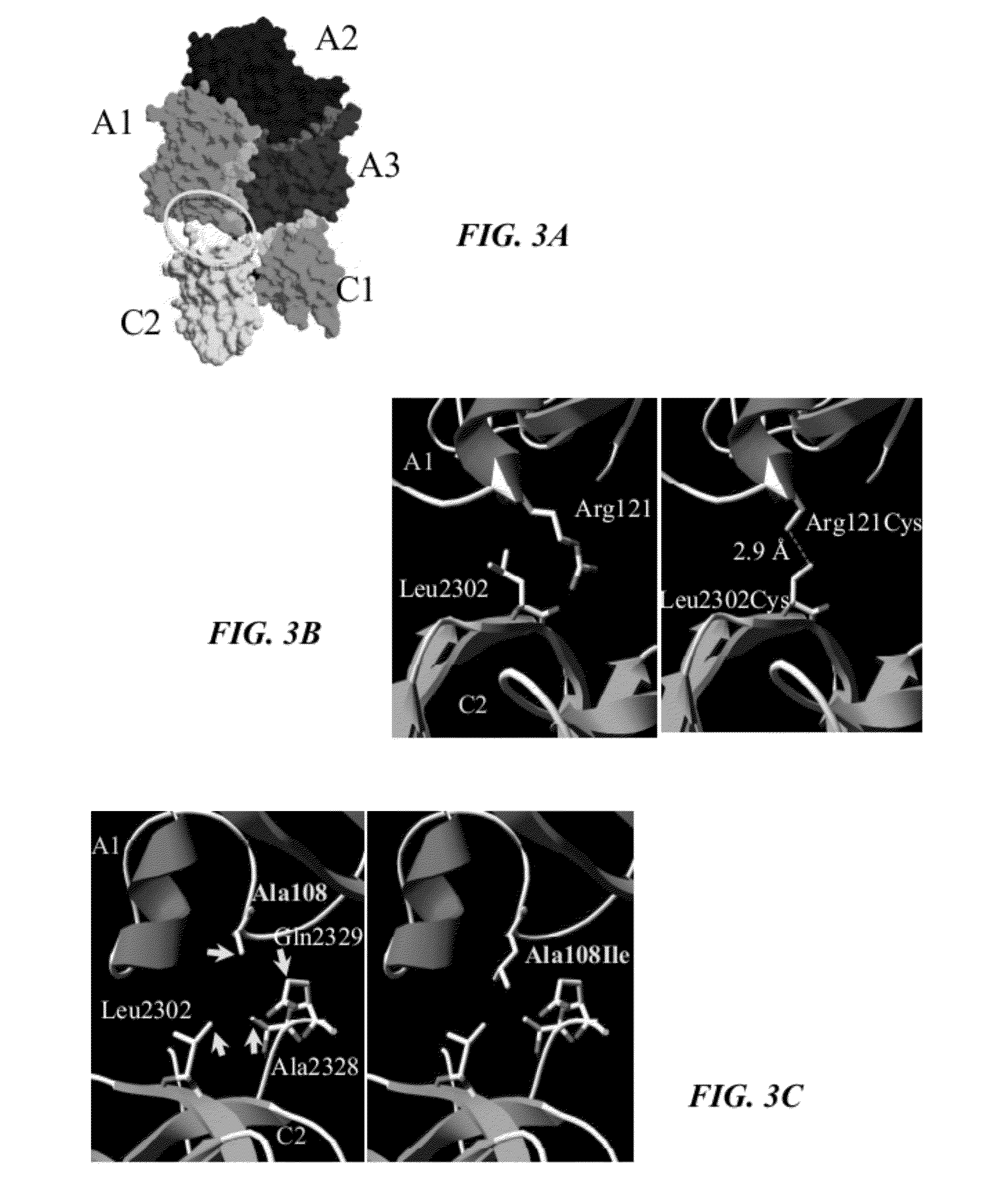
[0145]The A1 and C2 domains show close proximity to one another in the factor VIII crystal structure (FIG. 3A). These regions were investigated with the aim towards enhancing inter-domain interactions to positively alter affinity and stability parameters. Examination of the A1-C2 interface provided two possible approaches for increasing the inter-domain affinity. Although the orientation of side chains cannot be discerned due to the resolution (˜4 Å) of the structure (4), the putative spatial separation of several paired residues indicated that mutagenesis of these residues to Cys could result in formation of a nascent inter-domain disulfide bridge. Paired A1 / C2 domain residues were identified that appeared to meet this distance requirement and included Ser119 / Pro2300, Gln120 / Pro2299, Arg121 / Leu2302, Ala108 / Ala2328, and Trp106 / Ala2328.

[0146]Double mutations where each resi...

example 2

Confirmation of Disulfide Bridge in Arg121Cys / Leu2302Cys Factor VIII Variant

[0151]Evidence for high efficiency disulfide bridging between factor VIII A1 and A3C1C2 domains in this double mutant, as judged by Western Blotting is shown in FIG. 4. For this analysis, WT factor VIII and the Arg121Cys / Leu2302Cys factor VIII variant were cleaved with thrombin to generate the factor VIIIa heterotrimer prior to SDS-PAGE, which was then run in the absence and presence of disulfide bond reduction using DTT. Blots were probed with an anti-A1 antibody (58.12, lanes 1-4) and an anti-A3 antibody (2D2, lanes 5-8). Both A1 and A3C1C2 subunits derived from the factor VIII Arg121Cys / Leu2302Cys variant were detected at the ˜120 kDa band, consistent with the sum of their mol masses under non-reducing conditions (lanes 2 and 6), while reduction by 0.1 M DTT yielded the separated subunits (lanes 4 and 8). Based upon the band densities of bridged and free subunits in the non-reduced lanes, it appeared that...

example 3

Affinity of the WT and Ala108Ile Factor VIII Variant A1 Subunits for A3C1C2

[0152]To assess the affinity of the Ala108Ile A1 domain for C2 domain, the purified factor VIII variant and WT were treated with thrombin and the A1 subunits were separately purified as described supra. A1 subunits were then reacted with the environment-sensitive fluorescent probe, acrylodan, and these reagents were used to probe binding with the A3C1C2 subunit. The site for acrylodan attachment is likely the lone free thiol in A1 at Cys310, which is in close proximity (Structure 16:597-606 (2008), which is hereby incorporated by reference in its entirety). Indeed, increases in the emission fluorescence from acrylodan-labeled A1 (AcA1) subunit have been previously observed when A3C1C2 was bound to the molecule (Wakabayashi et al, “Metal-ion Independent Factor VIII Subunit Association and the Role of Calcium and Copper for Its Affinity and Activity,”Biochemistry 40:10293-10300 (2001); Ansong et al., “Factor VI...


PUM

PropertyMeasurementUnit
Molar densityaaaaaaaaaa

Abstract

The invention relates to a recombinant factor VIII that includes one or more mutations at an interface of A1 and C2 domains of recombinant factor VIII. The one or more mutations include substitution of one or more amino acid residues with either a cysteine or an amino acid residue having a higher hydrophobicity. This results in enhanced stability of factor VIII. Methods for making the recombinant factor VIII, pharmaceutical compositions containing the recombinant factor VIII, and use of the recombinant factor VIII for treating hemophilia A are also disclosed.

Description

[0001]This application claims the priority benefit of U.S. Provisional Patent Application Ser. No. 61 / 382,919, filed Sep. 14, 2010, which is hereby incorporated by reference in its entirety.[0002]This invention was made with government support under grant number HL38199 and HL76213 awarded by the National Institutes of Health. The government has certain rights in the invention.BACKGROUND OF THE INVENTION[0003]Hemophilia A, the most common of the severe, inherited bleeding disorders, results from a deficiency or defect in the plasma protein factor VIII. There is no cure for Hemophilia A and treatment consists of replacement therapy using preparations of (purified) plasma or the recombinant protein.[0004]Factor VIII circulates as a non-covalent, metal ion-dependent heterodimer. This procofactor form of the protein contains a heavy chain (HC) comprised of A1(a1)A2(a2)B domains and a light chain (LC) comprised of (a3)A3C1C2 domains, with the lower case a representing short (˜30-40 resid...

Claims


Application Information

Patent Timeline
IPC IPC(8): A61K38/37C12N15/11C12N15/63A61P7/04C12N1/21C12N1/19C07K14/755C12P21/00C12N5/10
CPCA61K38/00A61K38/37C07K14/755A61P7/04
Inventor FAY, PHILIP J.WAKABAYASHI, HIRONAO
Owner UNIVERSITY OF ROCHESTER
Why Eureka
Try Eureka