

Method and apparatus for producing toner
a technology of toner and production apparatus, applied in the direction of granulation using vibration, manufacturing tools, instruments, etc., can solve the problems of reducing the energy efficiency of production apparatus, and achieve the effect of high monodispersibility and efficient production of fine resin particles
- Summary
- Abstract
- Description
- Claims
- Application Information
AI Technical Summary
Benefits of technology
Problems solved by technology
Method used
Image

Examples
example 1
Preparation Step of Toner Composition Liquid
—Preparation of Colorant Dispersion Liquid—
[0325]Using a mixer having stirring blades, 17 parts by mass of carbon black (Regal400, product of Cabot Co.), 3 parts by mass of a pigment-dispersing agent (AJISPER PB821, product of Ajinomoto Fine-Techno Co., Ltd.) and 80 parts by mass of ethyl acetate were primarily dispersed. The obtained primary dispersion liquid was secondarily dispersed with DYNO MILL (NPM-PILOT, product of WAB Co.). Then, aggregates having a particle diameter of 5 μm or more were completely removed to prepare a colorant dispersion liquid.
—Preparation of Wax Dispersion Liquid—
[0326]Next, using a mixer having stirring blades, 18 parts by mass of carnauba wax, 2 parts by mass of a wax-dispersing agent and 80 parts by mass of ethyl acetate were primarily dispersed. Notably, the wax-dispersing agent used was a polyethylene wax to which a styrene-butyl acrylate copolymer had been grafted. The obtained primary dispersion liquid w...
example 2
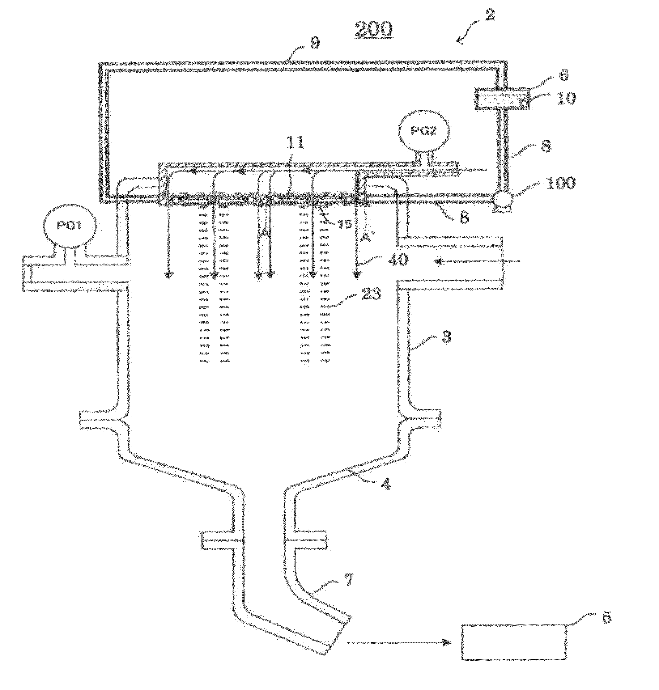
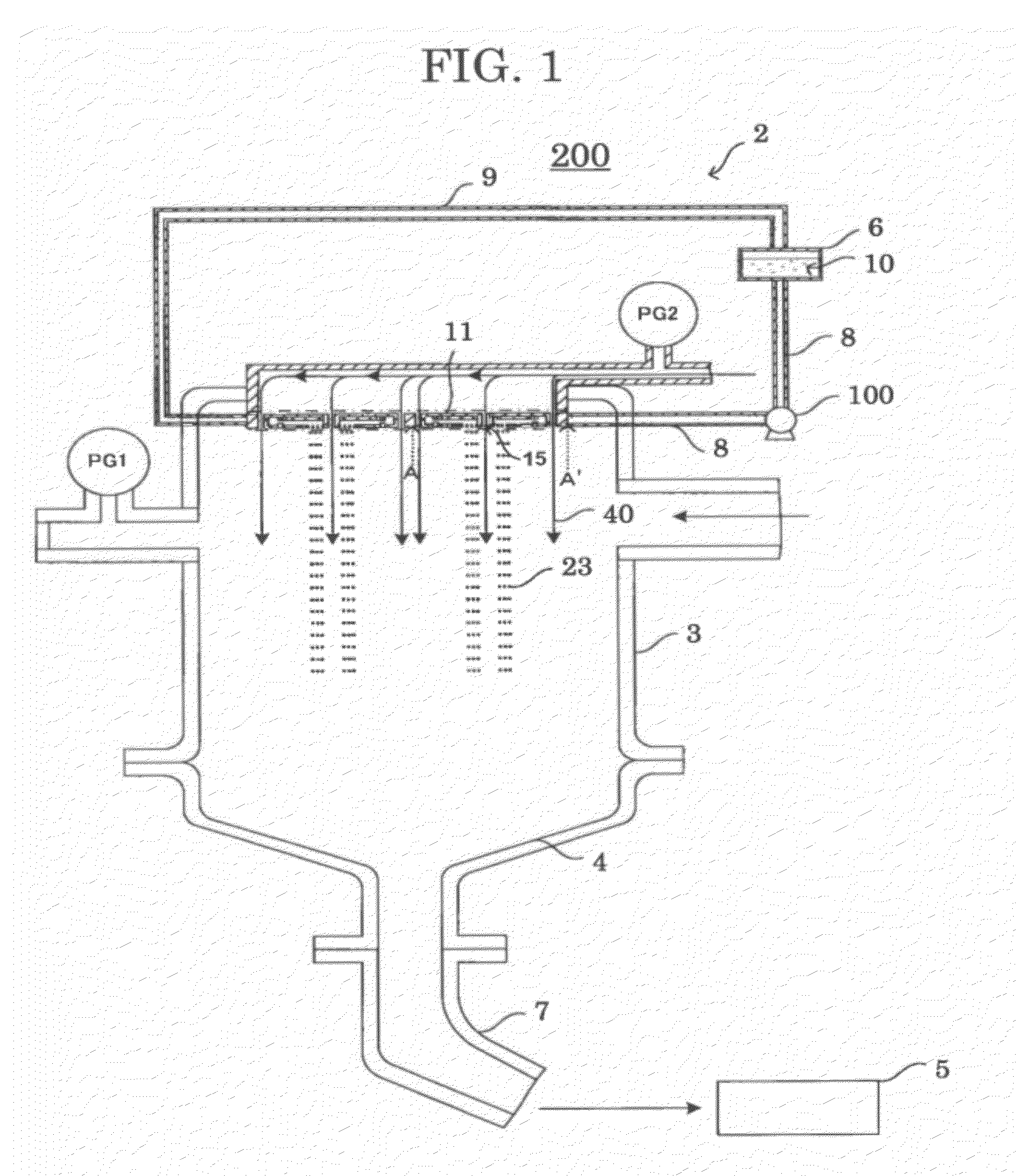
[0355]The procedure of Example 1 was repeated, except that the apparatus used was changed to an apparatus whose particle forming portion had a conveyance gas flow path and that the toner production conditions were changed to the following toner production conditions, to thereby produce a toner and a developer.
—Toner Production Conditions—
[0356]Specific gravity of toner composition dispersion liquid: ρ=1.19 g / cm3
[0357]Flow rate of conveyance gas flow: dry nitrogen gas in apparatus 30.0 L / min
[0358]Flow direction of conveyance gas flow: the same direction as the direction of the initial velocity of the discharged liquid droplets
[0359]Speed of conveyance gas flow: 15 m / sec
[0360]Inner temperature of particle forming portion: 27° C. to 28° C.
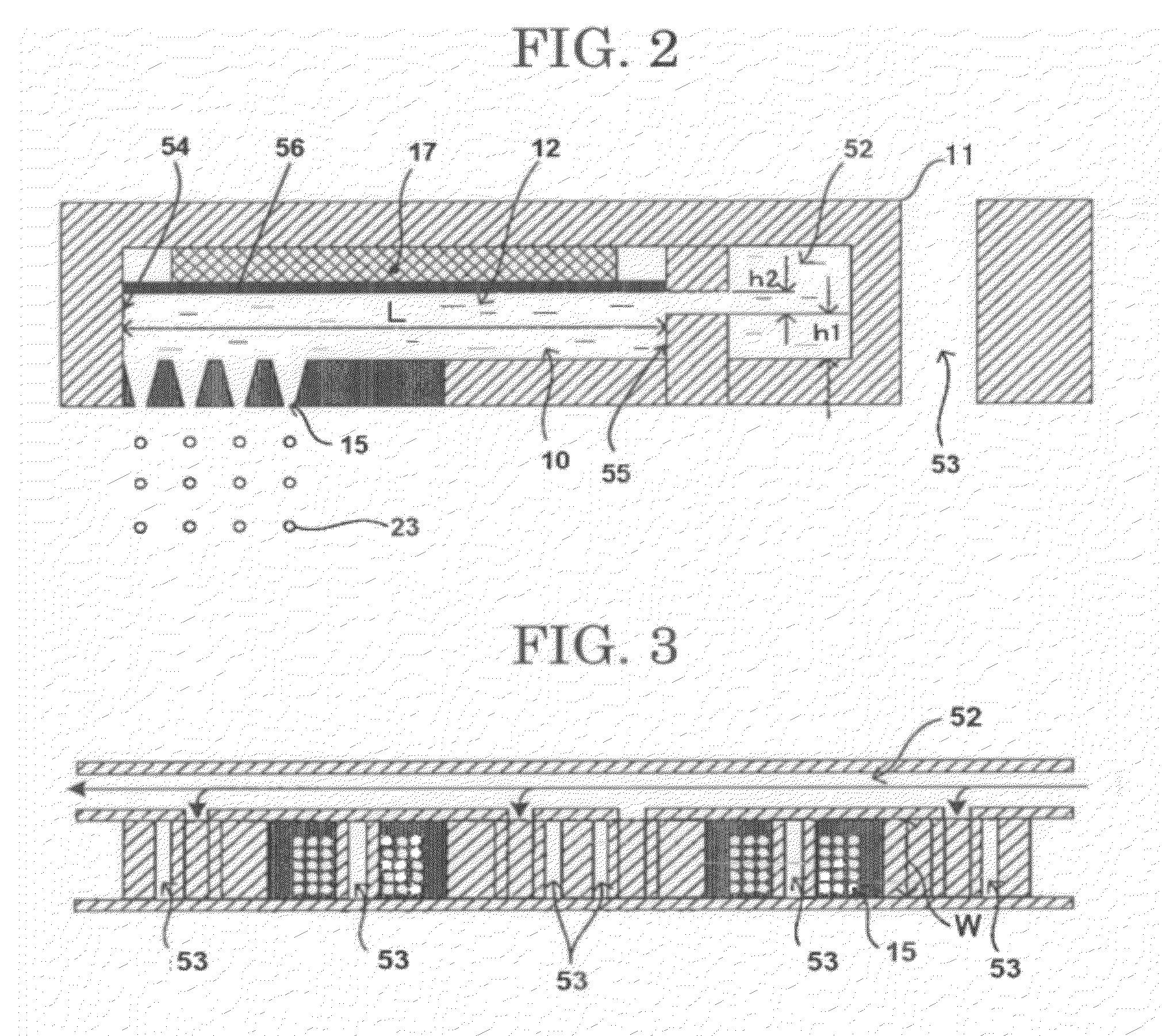
[0361]Vibration frequency of discharge holes: 125.0 kHz
[0362]p-p value of Sin wave of voltage applied to PZT: 43.5 V
[0363]The state where the toner composition dispersion liquid was discharged was observed using the LED and the CCD camera in the same...
example 3
[0367]The procedure of Example 2 was repeated, except that the toner production conditions were changed to the following toner production conditions, to thereby produce a toner and a developer.
—Toner Production Conditions—
[0368]Specific gravity of toner composition dispersion liquid: ρ=1.19 g / cm3
[0369]Flow rate of conveyance gas flow: dry nitrogen gas in apparatus 30.0 L / min
[0370]Flow direction of conveyance gas flow: the direction almost perpendicular to the direction of the initial velocity of the discharged liquid droplets
[0371]Speed of conveyance gas flow: 15 m / sec
[0372]Inner temperature of particle forming portion: 27° C. to 28° C.
[0373]Vibration frequency of discharge holes: 125.0 kHz
[0374]p-p value of Sin wave of voltage applied to PZT: 37.5 V
[0375]The state where the toner composition dispersion liquid was discharged was observed using the LED and the CCD camera in the same manner as in Example 1. Similar to Example 1, it was found that the toner composition dispersion liqu...
PUM
| Property | Measurement | Unit |
|---|---|---|
| Distance | aaaaa | aaaaa |
| Length | aaaaa | aaaaa |
| Length | aaaaa | aaaaa |
Abstract
Description
Claims
Application Information