Control device for vehicle

a control device and vehicle technology, applied in the direction of electric control, machines/engines, output power, etc., can solve the problems of difficult to ensure the production of sufficient heat, the quantity of heat supplied to the heater device will likely fall short, and the engine heat has decreased, so as to achieve comparatively easy control and complicated control

Active Publication Date: 2012-03-29
TOYOTA JIDOSHA KK
View PDF2 Cites 24 Cited by
  • Summary
  • Abstract
  • Description
  • Claims
  • Application Information

AI Technical Summary

Benefits of technology

[0010]In the present invention, the calculation result of the indication value of the prospective quantity of heat that will be needed by the heat consuming device, which uses the heat generated by the heat source mounted in the vehicle, is compared with the estimation result of the indication value of the prospective quantity of heat that will be suppliable by the heat source to the heat consuming device. If the prospective quantity of heat needed by the heat consuming device is less than the prospective quantity of heat that will be suppliable by the heat source to the heat consuming device, the increase request for the heat generation quantity is provided to the heat source control section, which controls the operating state of the heat source. In this manner, in the invention, it is determined whether the increase request for the heat generation quantity of the heat source should be generated based on comparison between the indication value of the prospective quantity of heat that will be needed by the heat consuming device and the indication value of the prospective quantity of heat that will be suppliable by the heat source to the heat consuming device. In response to the request for increasing the heat generation quantity, control is performed to increase the heat generation quantity of heat source. Accordingly, in the invention, heat generation increase control for the heat source is carried out only when the prospective quantity of heat that will be suppliable by the heat source to the heat consuming device is insufficient for the prospective quantity of heat that will be needed by the heat consuming device. As a result, the invention ensures a more efficient and adequate supply of the heat as required by the heat consuming device mounted in the vehicle.
[0012]To determine more accurately whether the quantity of heat transmitted from the heat source to the heat consuming device is sufficient, the necessary heat calculating section may be configured to calculate the indication value of the quantity of heat needed by the heat consuming device and the time at which this quantity of heat becomes necessary. Also, the heat supply estimating section may be configured to estimate the indication value of the quantity of heat that will be suppliable by the heat source to the heat consuming device at the calculated time. Alternatively, by configuring the heat supply estimating section to determine a prospective variation curve of the indication value of the quantity of heat that will be suppliable by the heat source to the heat consuming device, and estimate the indication value of the quantity of heat that can be supplied at the time with reference to the determined variation curve, it is determined more accurately whether the heat supply quantity is sufficient.
[0018]In the above-described invention, the temperature of the heat transmission medium necessary for ensuring the heat quantity required by the heat consuming device and the time at which this temperature becomes necessary are calculated by the necessary heat calculating section. Also, the temperature of the heat transmission medium at the aforementioned time in a case in which the heat source is operated continuously in the current operating state is estimated by the heat supply estimating section. If the temperature of the heat transmission medium estimated by the heat supply estimating section is lower than the temperature of the heat transmission medium calculated by the necessary heat calculating section, an increase request for the heat generation quantity of the heat source is provided to the heat source control section, which controls the operating state of the heat source. In other words, in the invention, determination of whether the quantity of heat generated by the engine is sufficient occurs after determination of a necessary temperature of the heat transmission medium and the time at which this temperature becomes necessary. As a result, the invention ensures more efficient and adequate supply of the heat needed by the heat consuming device mounted in the vehicle.
[0020]In this configuration, insufficiency in heat supply for the heat consuming device may be avoided by configuring the heat supply estimating section to estimate the temperature of the heat transmission medium on the assumption that the heat source will be operated under an operating condition with a small heat generation quantity.
[0024]When the heat generation increase control is executed in response to the increase request for the heat generation quantity from the heat generation increase requesting section, the operating state of the heat source may change and thus influence traveling of the vehicle. Also, operation of the heat source is controlled in response to other requests than the increase request for the heat generation quantity when the vehicle travels. Accordingly, if the heat generation increase control is carried out when the vehicle runs, adjustment must be performed between operating control on the heat source, which responds to the other requests, and the heat generation increase control, which complicates controlling. To solve this problem, the heat source control section may be configured to execute the heat generation increase control in response to the increase request for the heat generation quantity from the heat generation increase requesting section when the load required is zero. In this manner, the heat generation increase control is carried out comparatively easily without being limited by adjustment with respect to traveling of the vehicle or other operating controls.

Problems solved by technology

However, as engines have become more efficient and more compact to improve combustion performance, engine heat has decreased, thus making it difficult to ensure production of a sufficient quantity of heat.
The conventional control device for a vehicle increases the quantity of heat produced by the engine by raising the engine idle speed and retarding the ignition timing when it is determined that the engine coolant temperature is low and increases only with a small increase rate and thus the quantity of heat supplied to the heater device will likely fall short.

Method used


Image

  • Control device for vehicle
  • Control device for vehicle
  • Control device for vehicle

Examples


first embodiment

[0038]A first embodiment of the control device for a vehicle according to the present invention will hereafter be described with reference to FIGS. 2 to 5. Specifically, the present embodiment will be described as to, by way of example, a case in which the internal combustion engine mounted in the vehicle is the heat source and the heater core in the heater device for heating the passenger compartment is the heat consuming device.

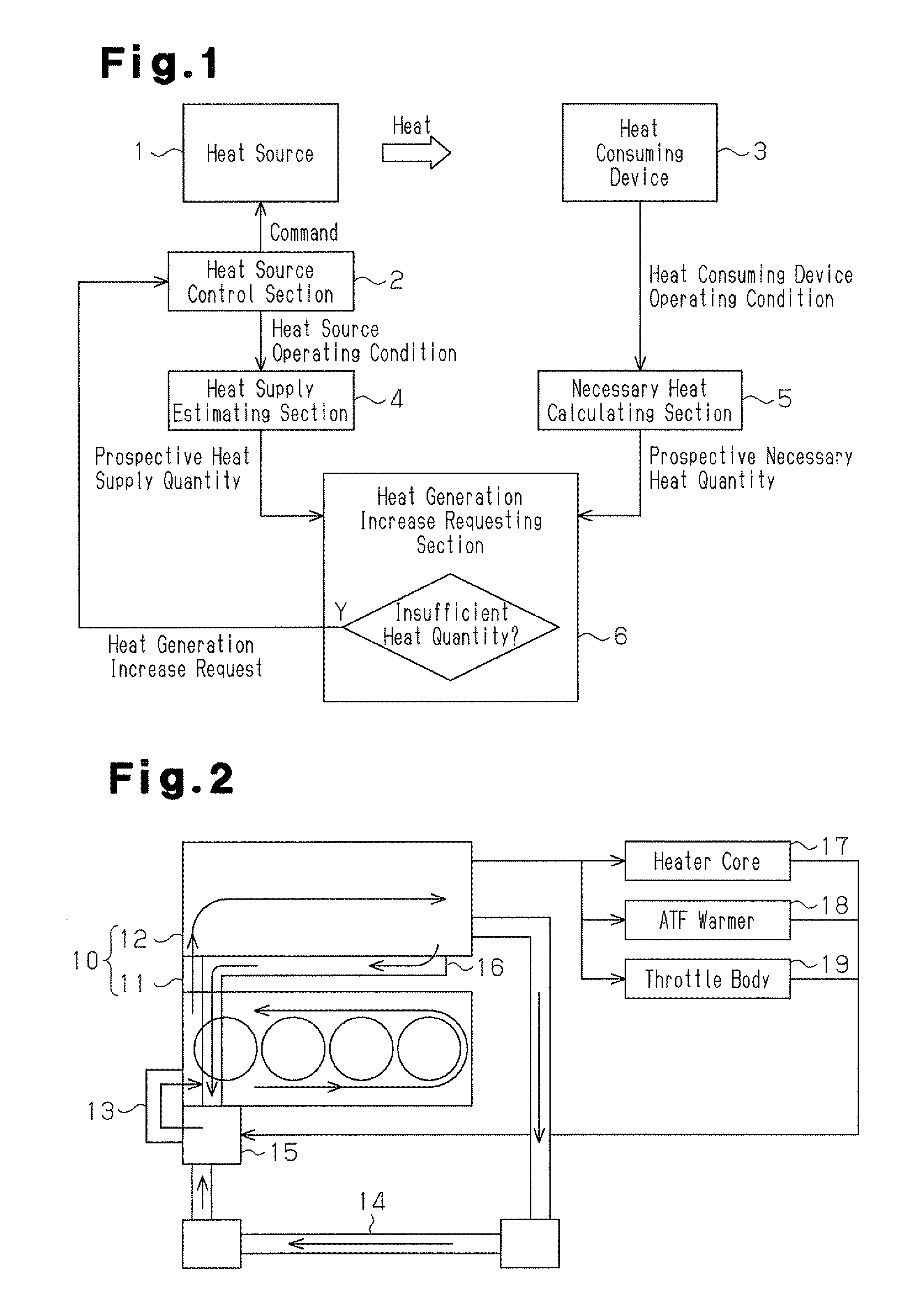
[0039]FIG. 2 represents the configuration of a cooling system in a vehicle employing the present embodiment. A water jacket is formed in a cylinder head 11 and a cylinder block 12 of an internal combustion engine 10 serving as a heat source. Coolant water circulates in the water jacket by means of a water pump 13.

[0040]After having passed through the cylinder head 11 and the cylinder block 12, the coolant water is cooled by a radiator 14 and returned to the engine 10 when the engine coolant temperature is sufficiently high. In contrast, if the engine coolan...

second embodiment

[0069]A second embodiment of the control device for a vehicle according to the invention will now be described in detail with reference to FIG. 6. Same or like reference numerals are given to components of the present embodiment and the other embodiments that will be described later that are the same as or like corresponding components of the above described embodiment. Detailed description of such components will be omitted.

[0070]When the heat generation increase control is performed in response to the heat generation increase request from the heat generation increase requesting section P3, the operating state of the engine 10 may change, thus influencing the travel of the vehicle. Also, when the vehicle runs, operation control is performed on the engine 10 in response to a request other than the heat generation increase request. The operation control may be, for example, torque demand control for adjusting output torque of the engine 10 in such a manner as to satisfy the torque re...

third embodiment

[0077]In the above described embodiments, the heat generation increase request control and the heat generation increase control according to the present invention are performed for the heat supply from the engine 10 to the heater core 17, which serves as the heat consuming device. However, the invention may be used also for heat supply from the engine 10 to a heat consuming device other than a heater core 17. The heat consuming device other than a heater core 17 may be, for example, an oil warmer for a transmission, a battery, a motor, a differential, a fuel cell stack, and a heat storage device.

[0078]In the present embodiment, the invention is employed for a heat storage device. The heat storage device in the present embodiment is configured as a heat insulation container for retaining engine coolant water. Specifically, the heat storage device stores heated engine coolant water from a previous running cycle of the vehicle and releases the stored heated coolant water into a coolant...


PUM


Abstract

By employing a heat source control section that controls the operating state of an internal combustion engine mounted in a vehicle, a necessary heat calculating section that calculates the engine coolant temperature needed by a heater core, which consumes the heat supplied from the engine through engine coolant water, and the time at which this engine coolant temperature becomes necessary, a heat supply estimating section that estimates engine coolant temperature at the aforementioned time in a case in which the engine is operated continuously in the current operating state, and a heat generation increase requesting section that requests the heat source control section to increase heat generation quantity of the engine when the engine coolant temperature estimated by the heat supply estimating section is less than the engine coolant temperature calculated by the necessary heat calculating section the heat necessary for the heater core is supplied more efficiently and adequately.

Description

TECHNICAL FIELD[0001]The present invention relates to a control device for a vehicle for allowing the vehicle to use heat efficiently.BACKGROUND ART[0002]A vehicle includes a number of devices that use heat produced by an internal combustion engine, such as a heater device or an oil warmer. However, as engines have become more efficient and more compact to improve combustion performance, engine heat has decreased, thus making it difficult to ensure production of a sufficient quantity of heat. To solve the problem, there is a demand for heat use efficiency to be improved.[0003]Conventionally, a control device described in Patent Document 1 has been proposed as a control device intended to ensure production of a necessary quantity of heat for a heater device for a vehicle having a low-displacement and low-heat-generation internal combustion engine. The control device described in Patent Document 1 carries out heat generation increase control by raising the engine idle speed and retard...

Claims


Application Information

Patent Timeline
Patent Type & Authority Applications(United States)
IPC IPC(8): B60H1/02
CPCF01P2003/028F01P2060/04F01P2060/08F02D13/0249F02D29/04Y02T10/18F02D2041/001F02D2200/022F02P5/1502Y02T10/46F02D41/021Y02T10/12Y02T10/40
Inventor MORITA, MASAKINAKAGAWA, TADASHIKISHITA, HIROSHI
Owner TOYOTA JIDOSHA KK
Why Eureka
Try Eureka