Permanent magnet machine with two stators

a permanent magnet machine and stators technology, applied in mechanical equipment, machines/engines, electric generator control, etc., can solve the problems of affecting the rotating machine and interconnected parts, causing practically the same problems, and disturbing the environment, and achieve high flexibility

Inactive Publication Date: 2012-03-29
SIEMENS AG
View PDF8 Cites 9 Cited by
  • Summary
  • Abstract
  • Description
  • Claims
  • Application Information

AI Technical Summary

Benefits of technology

[0018]One rotor may be provided for each stator. With two rotors two magnetic machines are arranged on the shaft. A generator can then be

Problems solved by technology

These torque pulsations may lead to vibrations which can be harmful to the rotating machine and interconnected parts.
Furthermore, the torque pulsations can create acoustic noise of low frequency which can disturb the environment.
In addition to the torque pulsations caused by tangential forces, radial

Method used


Image

  • Permanent magnet machine with two stators
  • Permanent magnet machine with two stators
  • Permanent magnet machine with two stators

Examples


Embodiment Construction

[0026]In the following detailed description, reference is made to the accompanying drawings which form a part hereof and in which are shown by way of illustration specific embodiments in which the invention may be practised. In this regard, directional terminology, such as “top” or “bottom” etc. is used with reference to the orientation of the Figure(s) being described. Because components of embodiments can be positioned in a number of different orientations, the directional terminology is used for purposes of illustration and is in no way limiting. It is to be understood that other embodiments may be utilized and structural or logical changes may be made without departing from the scope of the present invention. The following detailed description, therefore, is not to be taken in a limiting sense, and the scope of the present invention is defined by the appended claims.

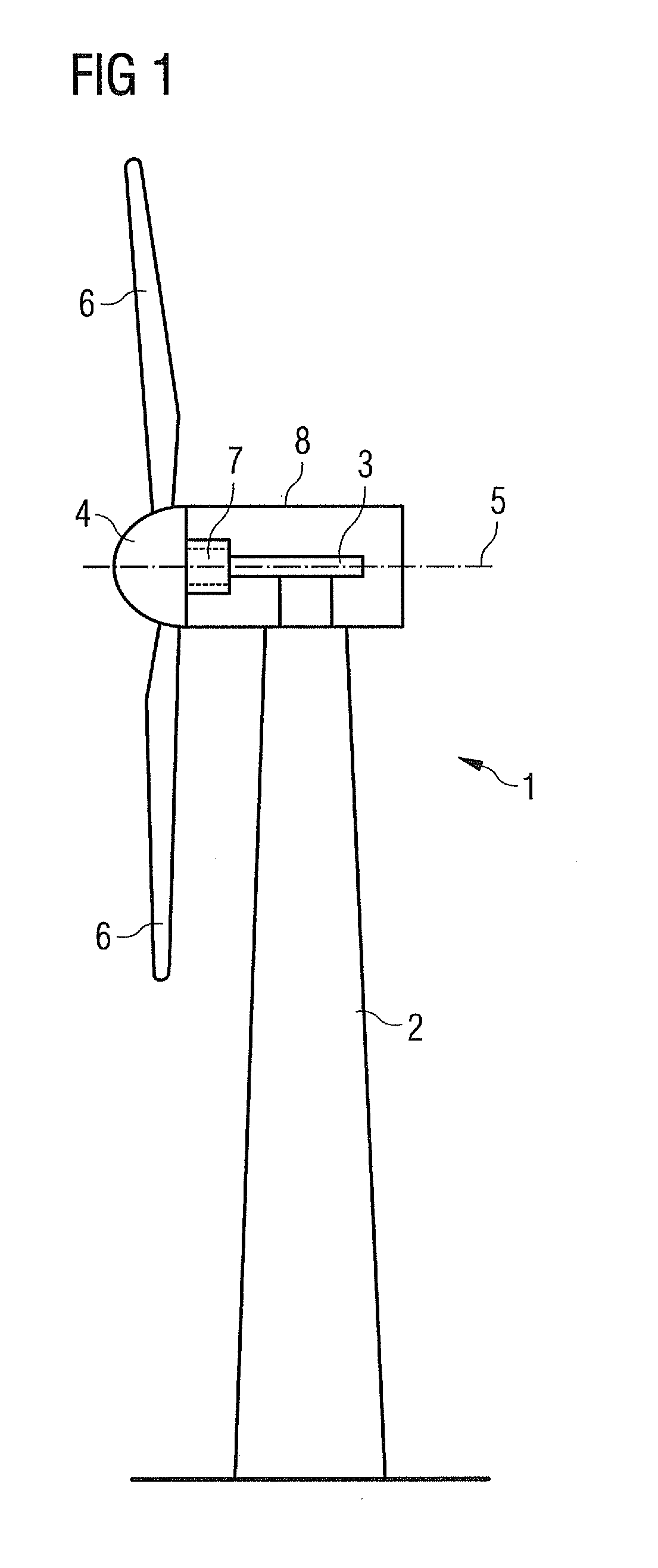
[0027]FIG. 1 shows a wind turbine 1 with a tower 2 fixed to the ground. The tower 2 can have a height of hundred m...


PUM


Abstract

A permanent magnet machine includes two stationary stators and a rotating rotor. Electromagnetic fields occurring in one stator are displaced by an angle of thirty electrical degrees with respect to electromagnetic fields occurring in the other stator due to currents fed to the stators.

Description

CROSS REFERENCE TO RELATED APPLICATIONS[0001]This application claims priority of European Patent Application No. 10179275.2 EP filed Sep. 24, 2010, which is incorporated by reference herein in its entirety.FIELD OF INVENTION[0002]The present invention relates in general to a permanent magnet machine with two stators. In particular, the present invention is directed to a generator of a wind turbine and a wind turbine with a permanent magnet machine with two stators.BACKGROUND OF INVENTION[0003]Due to variation in magnetic forces within rotating permanent magnet machines pulsations of torque occur. The torque pulsations occur at no-load and load situations, hereafter denoted cogging torque and ripple torque, respectively. These torque pulsations may lead to vibrations which can be harmful to the rotating machine and interconnected parts. Furthermore, the torque pulsations can create acoustic noise of low frequency which can disturb the environment. In addition to the torque pulsations...

Claims


Application Information

Patent Timeline
IPC IPC(8): F03D9/00H02K16/04
CPCH02K7/1838Y02E10/725H02K29/03H02K16/00Y02E10/72H02K16/04
Inventor PEDERSEN, KENNETH
Owner SIEMENS AG
Why Eureka
Try Eureka