

Polarized light source and polarization converting method and device thereof
a technology of polarized light and conversion method, which is applied in the direction of polarizing elements, lighting and heating apparatus, instruments, etc., can solve the problems of inability to output a stable linear polarized light, and achieve the effects of improving the light utilization efficiency of projection systems, improving conventional technology, and improving power and brightness of output ligh
- Summary
- Abstract
- Description
- Claims
- Application Information
AI Technical Summary
Benefits of technology
Problems solved by technology
Method used
Image

Examples
first embodiment
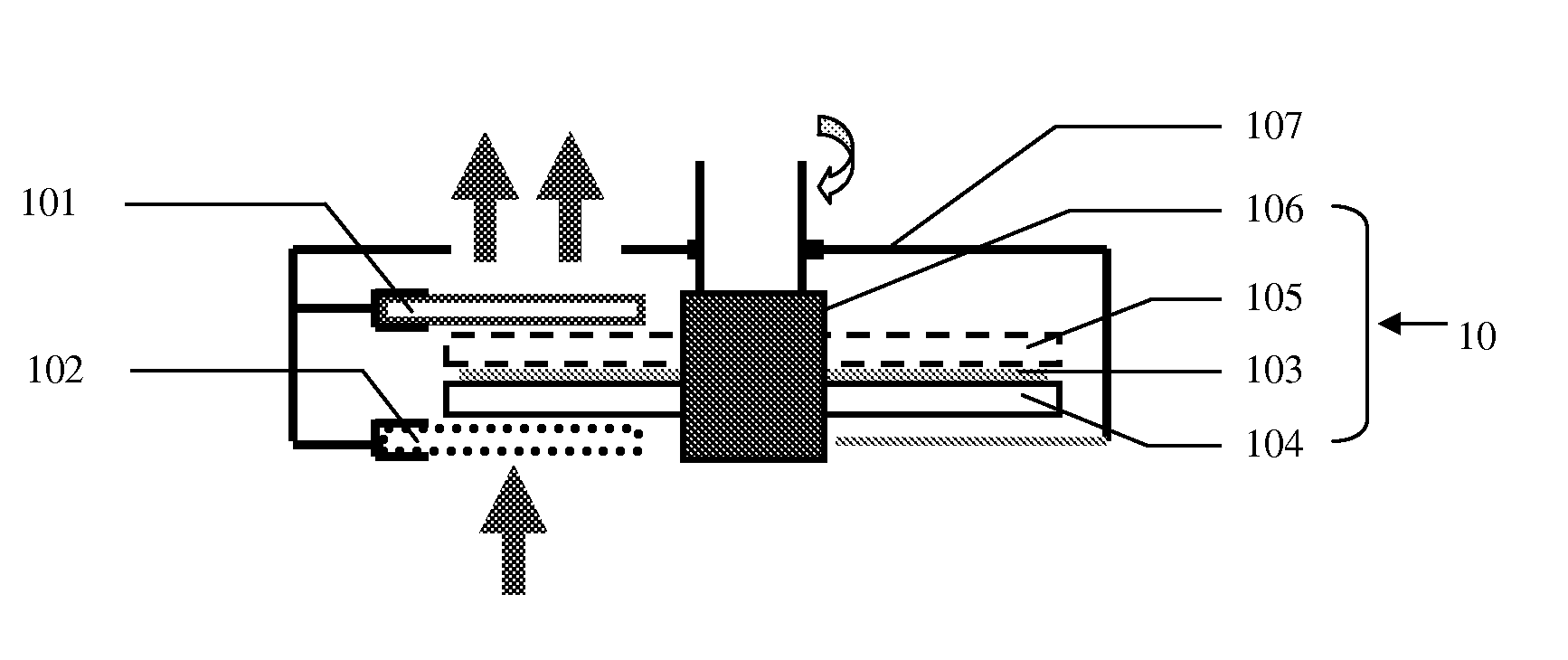
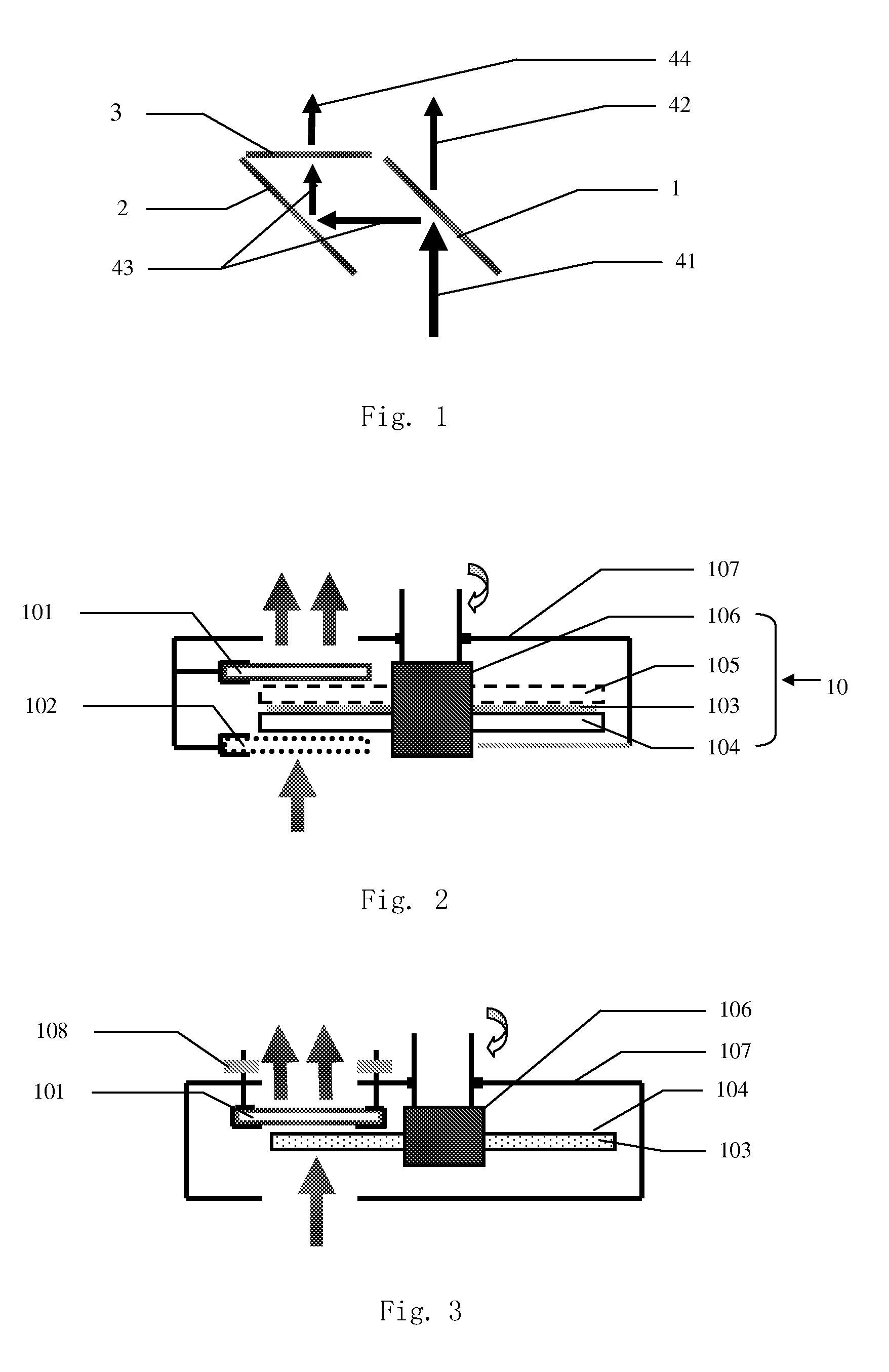
[0036]FIG. 2 is cross-sectional view illustrating a polarization conversion device according to the present invention. The polarization conversion device includes a stationary member 107 and a rotating device 10. The rotating device 10 includes a moveable carrier 104 which moves relative to the stationary member 107. The moveable carrier 104 is made of a transparent material and carries one or more wavelength conversion materials 103. The stationary member 107 may be a cover or housing for the rotating device 10, and a rotational shaft 106 of the rotating device is rotatably mounted on the stationary member 107 via bearings or the like. The wavelength conversion materials 103 may be mixed into a gel and adhered to one side of the moveable carrier 104. Alternatively, the wavelength conversion materials 103 may be sandwiched between the moveable carrier 104 and a transparent plate 105 (shown in dashed lines), such as a low cost glass. One or both sides of the transparent plate 105 and...
second embodiment
[0040]FIG. 3 shows a polarization conversion device according to the present invention. In this embodiment, the wavelength conversion materials 103 are mixed into the transparent material that forms the moveable carrier 104. For example, the moveable carrier 104 may be a glass substrate with phosphor powders mixed therein, forming a sufficiently strong moving body.
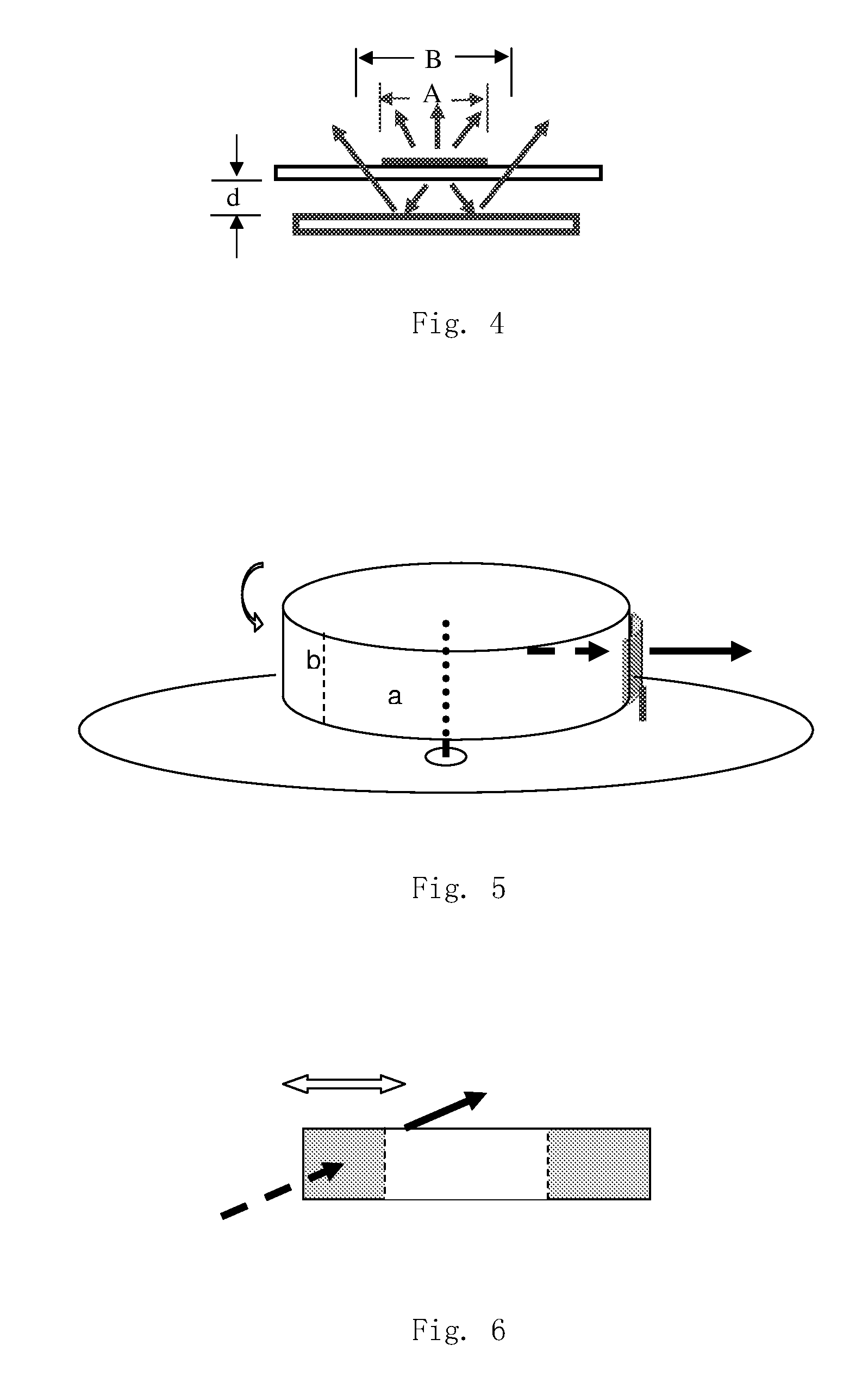
[0041]As it is desirable to reduce the size of the polarization beam splitter 101 as much as possible to reduce cost, the distance between the polarization beam splitter 101 or the filter 102 and the moveable carrier 104 should be accurately controlled, especially when the light spot of the excitation light on the moveable carrier 104 is very small. Referring to FIG. 4, where d represents the distance between an optical component (the polarization beam splitter 101 or the filter 102) and the moveable carrier above the optical component. If the optical component represents the filter, then after the filter reflects the conv...
PUM
 Abstract
Description
Claims
Application Information