Pulsed light optical rangefinder

a technology of optical rangefinders and pulsed light, which is applied in the field of cameras, can solve the problems of complex system, complicated and costly optics for separating light, and the inability to expand the dynamic range of the whole monolith array, so as to reduce the photon detection rate of the receiver, increase the dynamic range, and prevent saturation

Active Publication Date: 2012-03-29
TOYOTA JIDOSHA KK
View PDF6 Cites 101 Cited by
  • Summary
  • Abstract
  • Description
  • Claims
  • Application Information

AI Technical Summary

Benefits of technology

[0014]By controlling the detection probability according to a light level, the receiver can have an increased dynamic range. This can apply even while detecting very weak signals since the receiver can still be in a photon counting mode while the detection probability is controlled. This can apply even while being subject to heavy sunshine, since the photon detection rate of the receiver can be lowered, so as to prevent saturation. Besides, reflective power from an object depends on distance and reflectivity of the object. Methods and apparatus according to the present invention can operate independently of such object properties. Embodiments of the present invention can be simpler and cheaper than using optical components to increase the dynamic range. The light level can be indicated by counting an output of the receiver itself during a predefined duration, or by another detector external to the receiver, or in any other way.
[0015]Advantages of embodiments of the present invention include a significant improvement of dynamic range of an optical rangefinder such that dynamic range need not be a limitation any longer.

Problems solved by technology

Thus, it is impossible to expand the dynamic range of whole the monolith array.
The method of ref 2 can expand the dynamic range, even in the case of a monolithic array, however complicated and costly optics for separating light are required.
Although the method of ref 2 can easily switch the mode by changing reverse bias voltage, the system is complicated due to needing two different kinds of signal processing for the different modes.

Method used


Image

  • Pulsed light optical rangefinder
  • Pulsed light optical rangefinder
  • Pulsed light optical rangefinder

Examples


second embodiment

FIG. 6, Second Embodiment, Alternative Configuration of Receiver, Using Shift Register,

[0065]A second embodiment is shown in FIG. 6. The counter in FIG. 3 is replaced with an M-bit shift register 470 and an adder 475. The CLK1 is delayed for one pulse by delay element 365 and is input to the shift register. The shift register is updated with a period of T. When a pulse is input from the APD, upper 1 bit becomes 1, and when the shift register is updated, the lower 1 bit is discarded. The M bit shift register is always storing the M latest periods of information denoting existence of a pulse. At every pulse illumination, the adder counts a number of bits set at 1, and outputs it to the comparator. Operation of the comparator is the same as that in FIG. 3, but the period of EN is T instead of MT. Consequently, an update period of Vc is shortened by a factor of M and it is capable of adjusting more rapidly to follow sudden changes of incident light, and e.g. as well as noise level.

third embodiment

FIG. 7, Third Embodiment, Alternative Configuration Using Differential Counter

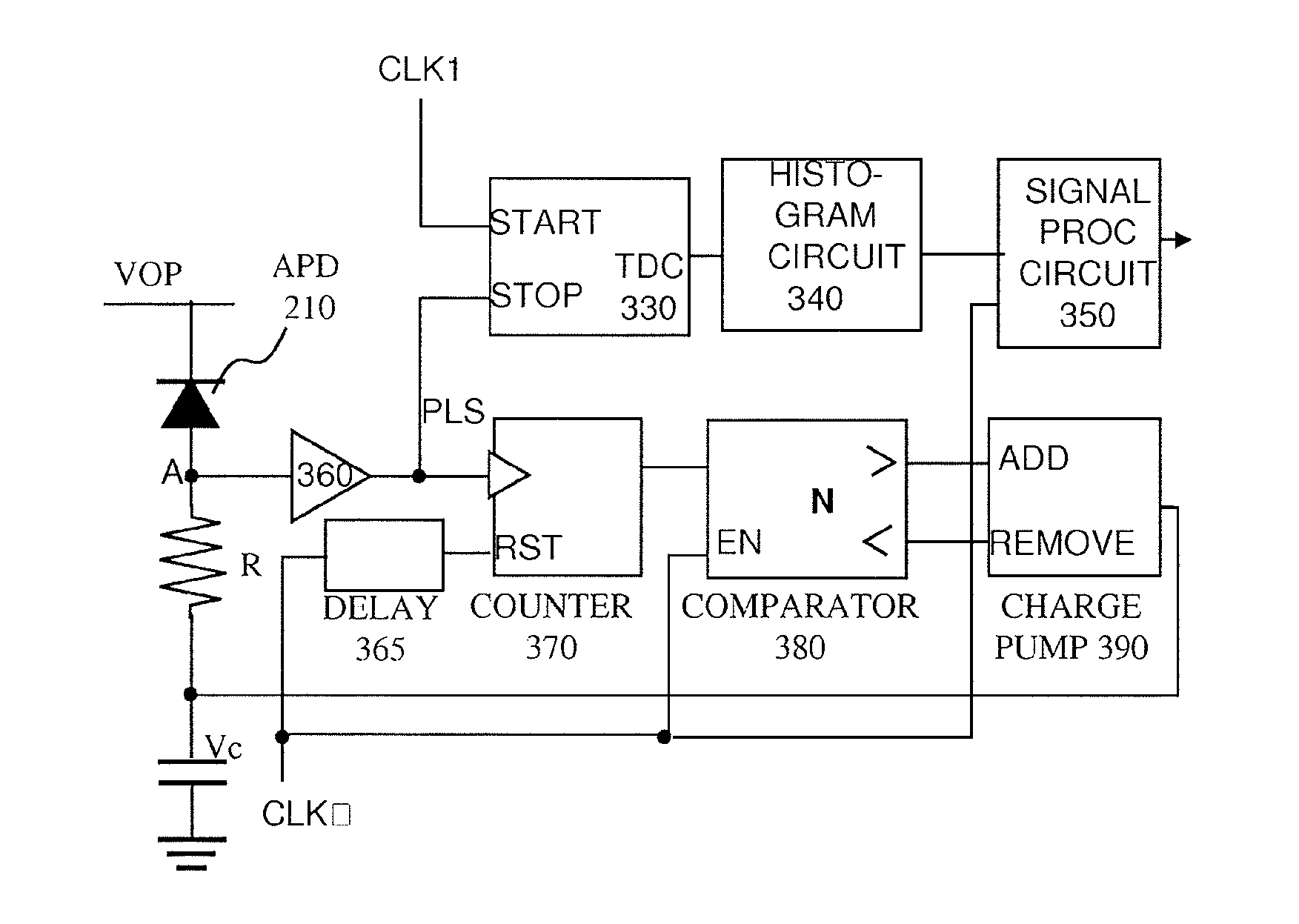
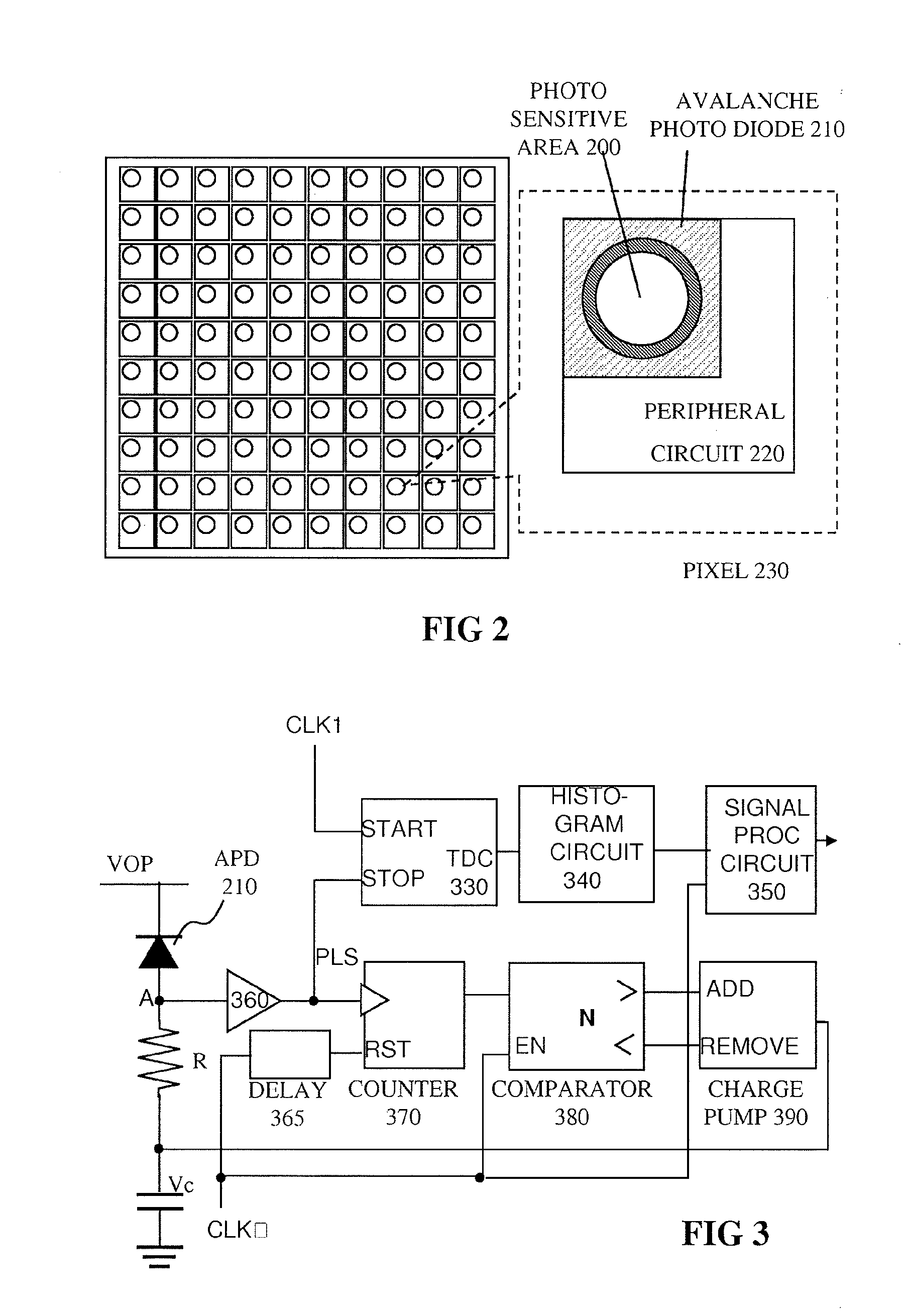
[0066]A third embodiment is shown in FIG. 7, in which the counter and comparator in FIG. 3 are replaced with a differential counter 570. The differential counter is incremented when a PLS from APD is input, and is decremented when a TRG is input. When EN is input, the sign of the counted number is output. If a photon detection cycle is longer than a TRG cycle, the accumulated count is positive, and Vc is lowered by the charge pump. Since the reverse bias voltage is increased, the photo detection probability is enhanced. If a photon detection cycle is shorter than a TRG cycle, the operation is reversed. Consequently, the reverse bias voltage can be controlled with the aim of equalizing the cycle of photon detection and TRG. The target cycle for photon detection can be easily set by changing the TRG cycle. Updating the cycle of Vc can also be done by changing a cycle of EN, and thus faster control of Vc is f...


PUM


Abstract

An optical rangefinder based on time-of-flight measurement, radiates pulsed light toward an object (70), and receives reflected light from the object, the receiver operating in a photon counting mode, so as to generate a pulse for a detected photon. There is a variable probability of a photon detection on the receiver, and a controller (370, 380, 390; 365, 470, 475, 380, 390; 570, 580, 590, 390) controls the photon detection probability of the receiver, based on a light level. By controlling the detection probability according to a light level, the receiver can have an increased dynamic range, and without the expense of using optical components. This can apply even while detecting very weak signals since the receiver can still be in a photon counting mode while the detection probability is controlled. The light level can be indicated by an output of the receiver itself, or by another detector external to the receiver.

Description

FIELD OF THE INVENTION[0001]This invention relates to cameras and in particular to optical rangefinders, to methods of operating such rangefinders, and to receivers for use in such methods and to corresponding controllers. In particular the present invention can find advantageous use in automotive applications.DESCRIPTION OF THE RELATED ART[0002]It is known to provide an optical rangefinder based on TOF (Time Of Flight) in the form of a device to detect a distance by measuring a elapse time between illuminated light and reflected time. Though both reflected light (signal) and background light (noise) are detected, the signal component can be extracted by eliminating noise light with signal processing. For operation in outdoor or other bright conditions, a large dynamic range is required due to significant brightness difference between day time and night time. In order to achieve wide dynamic range, two methods of dynamic range expansion for a TOF based optical rangefinder are known....

Claims


Application Information

Patent Timeline
Patent Type & Authority Applications(United States)
IPC IPC(8): G01S7/487G01S17/89G01S7/4863G01S17/10
CPCG01S7/4814G01S7/4816G01S7/4863G01S17/89G01S7/489G01S7/497G01S7/487G01S17/10G01S7/4868G01S7/4818
Inventor NICLASS, CRISTIANOCHARBON, EDOARDOSOGA, MINEKIYANAGIHARA, HIROMICHI
Owner TOYOTA JIDOSHA KK
Why Eureka
Try Eureka