Solar cell module
- Summary
- Abstract
- Description
- Claims
- Application Information
AI Technical Summary
Benefits of technology
Problems solved by technology
Method used
Image

Examples
first embodiment
Schematic Structure of Solar Cell Module
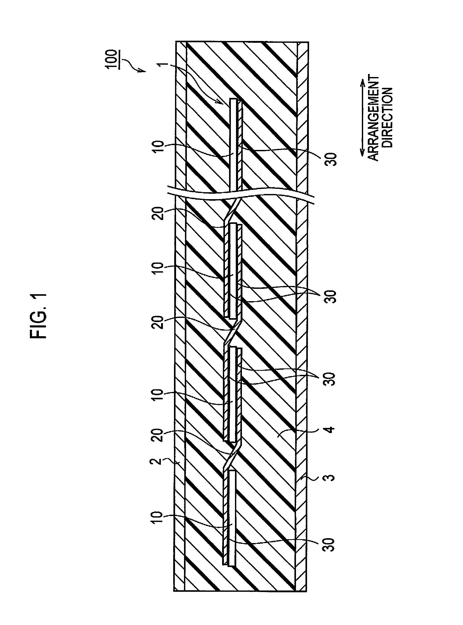
[0043]A schematic structure of a solar cell module 100 according to the embodiment will be described with reference to FIG. 1. FIG. 1 is a side view of the solar cell module 100 according to the present embodiment.
[0044]The solar cell module 100 is provided with a solar cell string 1, a light-receiving-surface-side protection member 2, a back-surface-side protection member 3 and a sealing material 4. The solar cell module 100 is constituted by sealing the solar cell string 1 between the light-receiving-surface-side protection member 2 and the back-surface-side protection member 3.
[0045]The solar cell string 1 is provided with a plurality of solar cells 10, a wiring member 20 and an adhesive 30. The structure of the solar cell string 1 will be described later.
[0046]A plurality of solar cells 10 are arranged along an arrangement direction. Each of a plurality of solar cells 10 includes a light-receiving surface to which sunlight enters and a bac...
second embodiment
[0089]Hereinafter, a solar cell string 1 according to a second embodiment of the present invention will be described with reference to the drawings. FIG. 6 is an enlarged plan view of the solar cell string 1 according to the second embodiment seen from the light-receiving surface side.
[0090]As illustrated in FIG. 6, a cross electrode 13 includes a crossing portion 13a which is a portion crossing one thin line electrode 12 of a plurality of thin line electrodes 12, and an extending portion 13b extending from the crossing portion 13a. The line width αw1 of the crossing portion 13a is greater than the line width αw2 of the extending portion 13b. That is, the cross electrode 13 is formed to increase in the line width at the portion in which the cross electrode 13 crosses each of a plurality of thin line electrodes 12.
[0091]Although the crossing portion 13a is provided at a bending portion of the cross electrode 13 in FIG. 6, this is not restrictive. In a case in which a linear portion o...
example 1
[0104]First, a plurality of photovoltaic converting units (125 mm in square and 200 micrometers in thickness) having a structure which is called the “HIT” (registered trademark; SANYO Electric Co., Ltd.) structure were prepared.
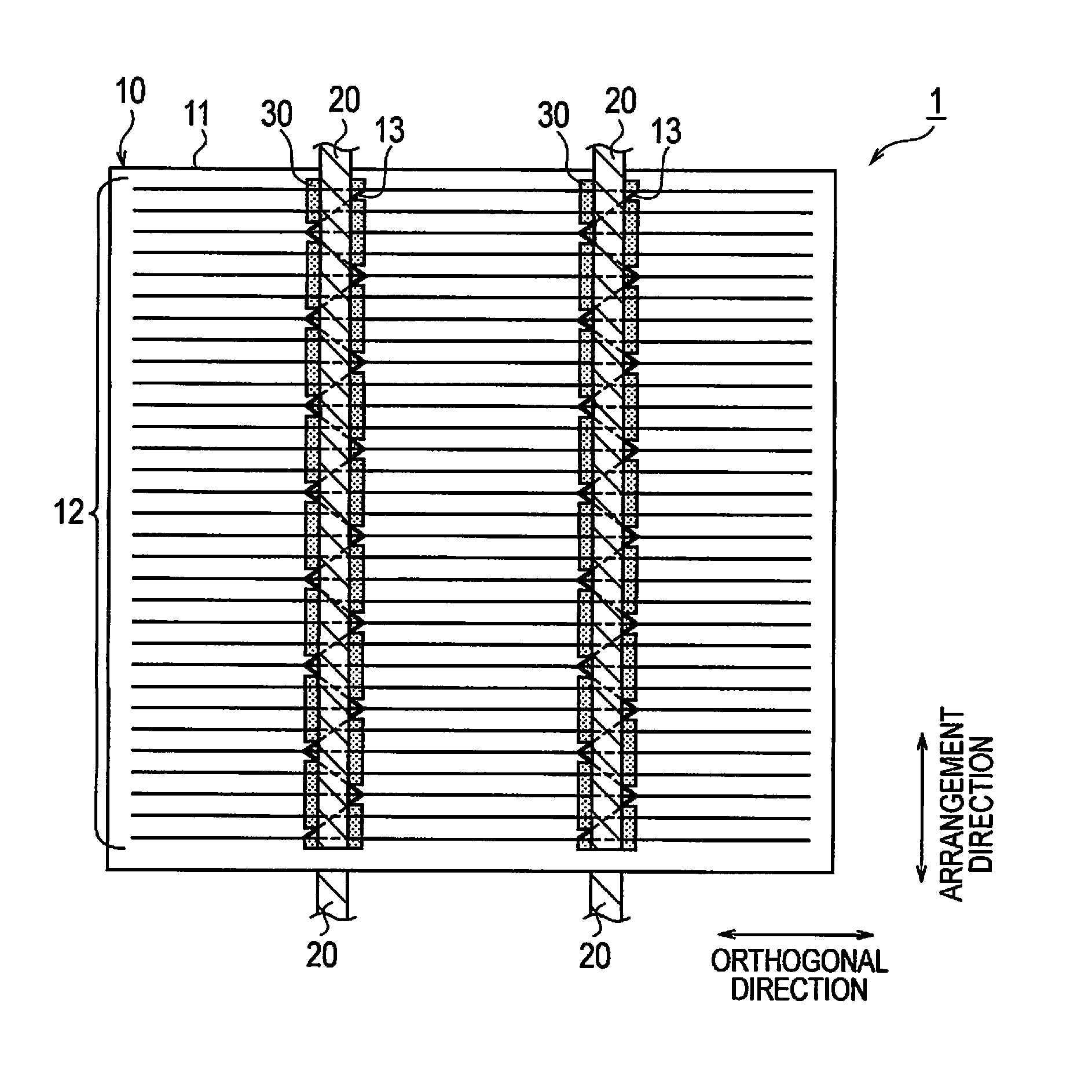
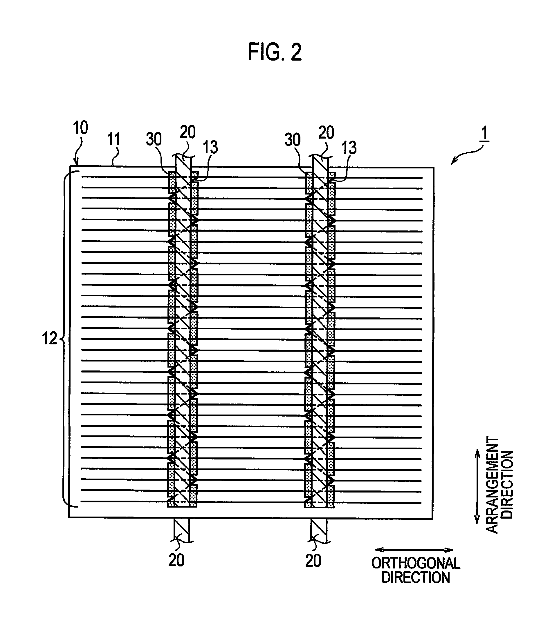
[0105]Next, a plurality of thin line electrodes (line width: 100 micrometers, pitch: 2 mm) and the cross electrode (line width: 120 micrometers, orthogonal direction width: 2 mm) were formed by printing a silver paste once by means of offset printing on the light-receiving surface of each of a plurality of photovoltaic converting units. A formed pattern of the electrode was the pattern illustrated in FIG. 2. Subsequently, the conductive paste on the light-receiving surface was dried under a predetermined condition.
[0106]Next, a plurality of thin line electrodes (line width of 100 micrometers, pitch of 1 mm) and cross electrode (line width of 120 micrometers, and orthogonal direction 2 mm in width) were formed by printing silver paste once with offset printing...
PUM
 Abstract
Description
Claims
Application Information
 - R&D
- Intellectual Property
- Life Sciences
- Materials
- Tech Scout
- Unparalleled Data Quality
- Higher Quality Content
- 60% Fewer Hallucinations
Browse by: Latest US Patents, China's latest patents, Technical Efficacy Thesaurus, Application Domain, Technology Topic, Popular Technical Reports.
© 2025 PatSnap. All rights reserved.Legal|Privacy policy|Modern Slavery Act Transparency Statement|Sitemap|About US| Contact US: help@patsnap.com