
Universal automotive ignition pickup assembly

a technology of capacitive inductive ignition and automotive ignition, which is applied in the direction of engine ignition, machine/engine, mechanical equipment, etc., can solve the problems of low resistance, difficult to acquire and monitor ignition voltage waveforms from all of these different ignition systems, and undesirable engine misfires, etc., to achieve the effect of enhanced ability of ignition pickup, and convenient use of universal automotive ignition pickup assembly

Inactive Publication Date: 2012-04-05
THOMPSON BERNIE C +1
View PDF3 Cites 12 Cited by
  • Summary
  • Abstract
  • Description
  • Claims
  • Application Information

AI Technical Summary

Benefits of technology

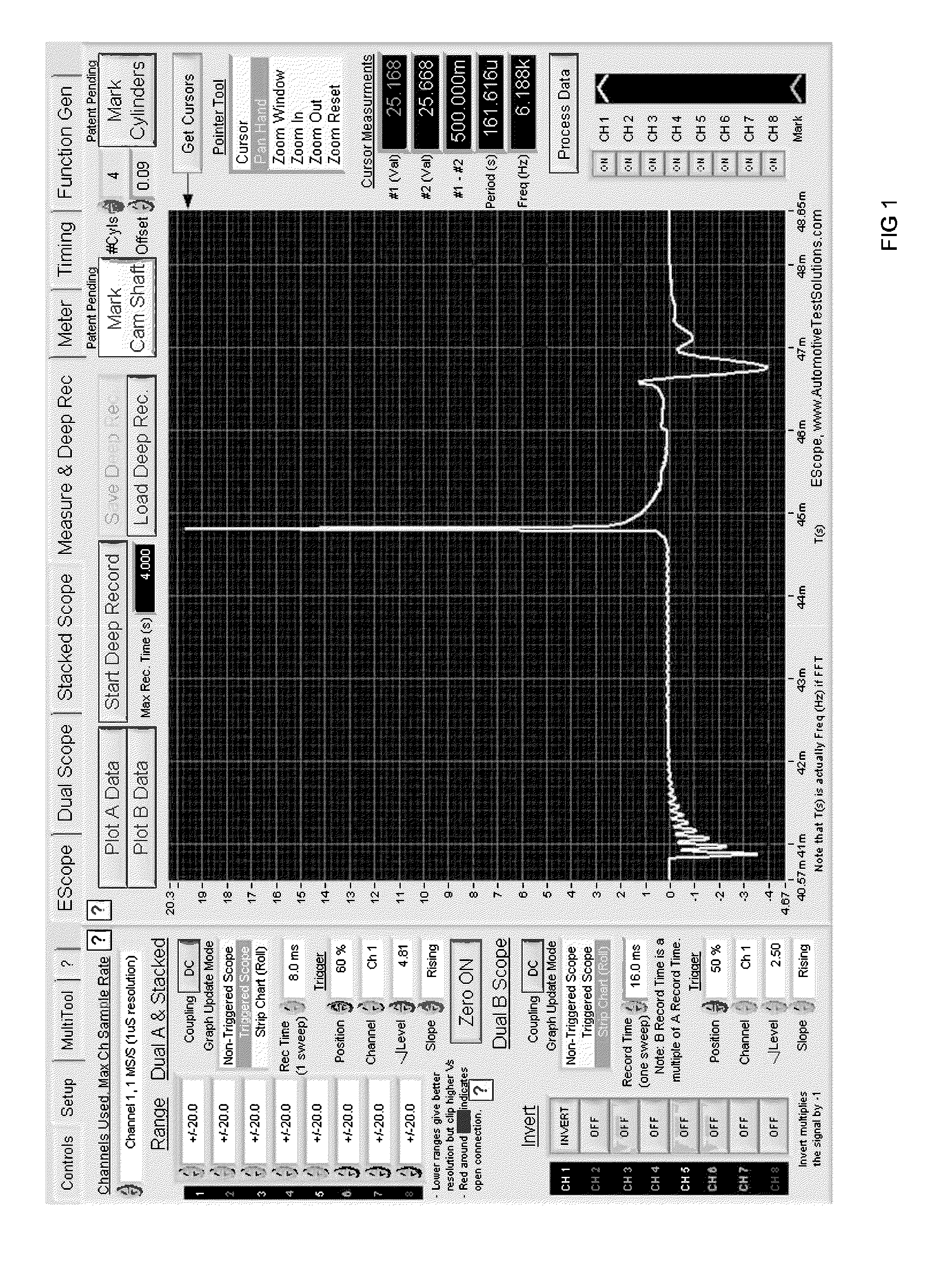
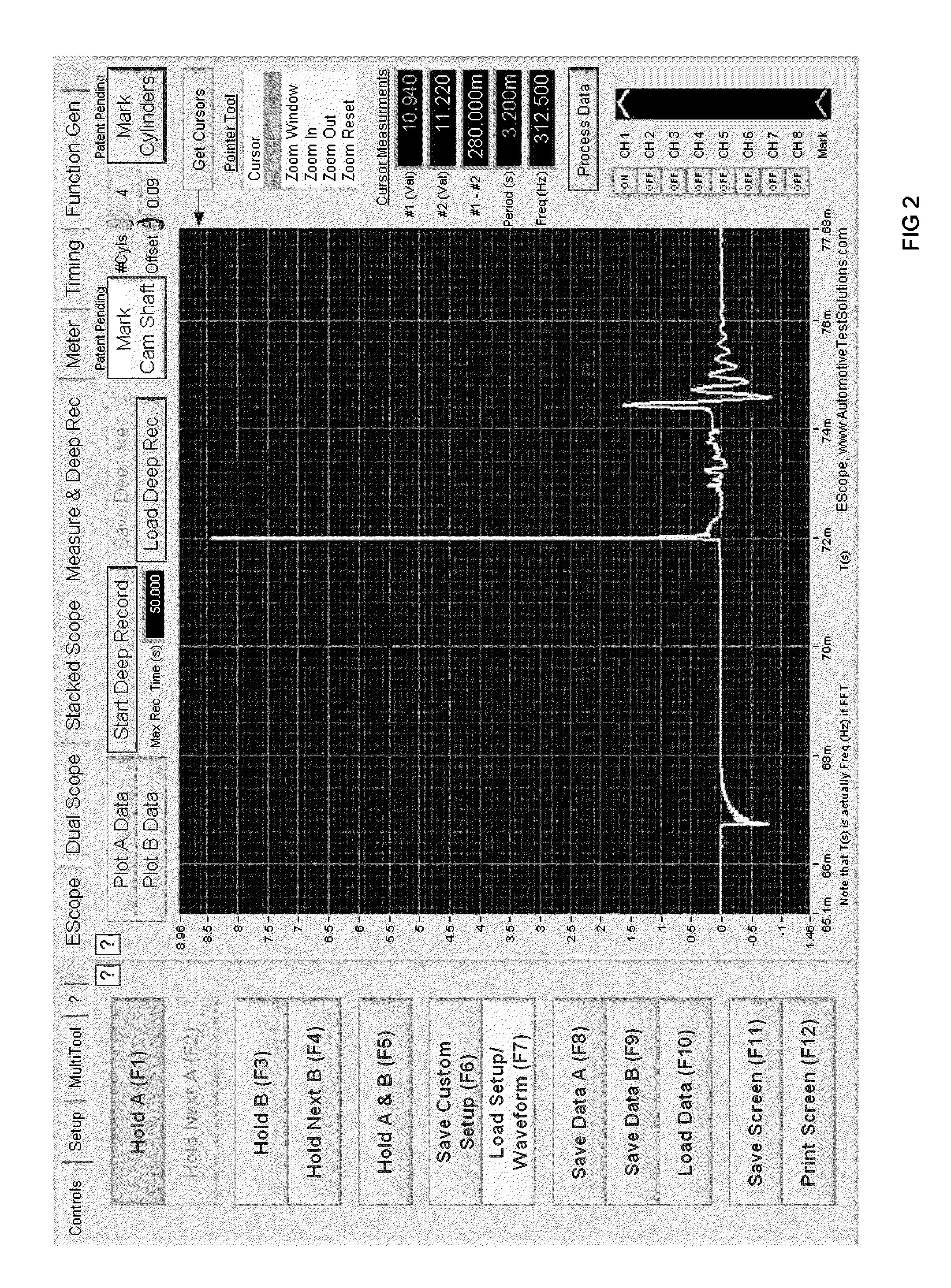
[0018]This is accomplished with a sensing probe that can be capacitive coupled; inductively coupled; or capacitive and inductively coupled at the same time. Due to the ability of a pickup to be capacitive and inductive at the same time, the ignition voltage waveforms are clear and concise from secondary ignition wires to a multitude of different ignition coil types. FIG. 1, FIG. 2, FIG. 3, FIG. 4 shows the invention working on a multitude of different systems. The ability of the ignition pickup is enhanced by a method to easily adapt the pickup by attaching either to a secondary ignition wire; or to many different types, configurations, and sizes of ignition coils. These unique abilities of the invention make the use of the Universal Automotive Ignition Pickup Assembly quite easy.

Problems solved by technology

These voltage changes indicate how the combustion process occurred and shows problems such as; lean air fuel mixture, rich air fuel mixture, carbon traces, arcing outside the combustion chamber, weak spark discharge, high resistance in secondary circuit, low resistance in secondary circuit, and turbulence from engine mechanical problems.
When a problem occurs to ignite this air-fuel charge an unwanted engine misfire will occur.
Many new ignition systems have emerged over the years making it very difficult to acquire and monitor ignition voltage waveforms from all of these different ignition systems.
The ignition pickups that are currently available cannot provide ignition signals from all of these different ignition systems.
As seen in the prior art, these ignition diagnostic systems are specific to certain ignition systems and are not generic nor wide based.
In fact the prior art is very limited and inadequately addresses the automotive industry's need for an ignition pickup.

Method used


Image

  • Universal automotive ignition pickup assembly
  • Universal automotive ignition pickup assembly
  • Universal automotive ignition pickup assembly

Examples


Embodiment Construction

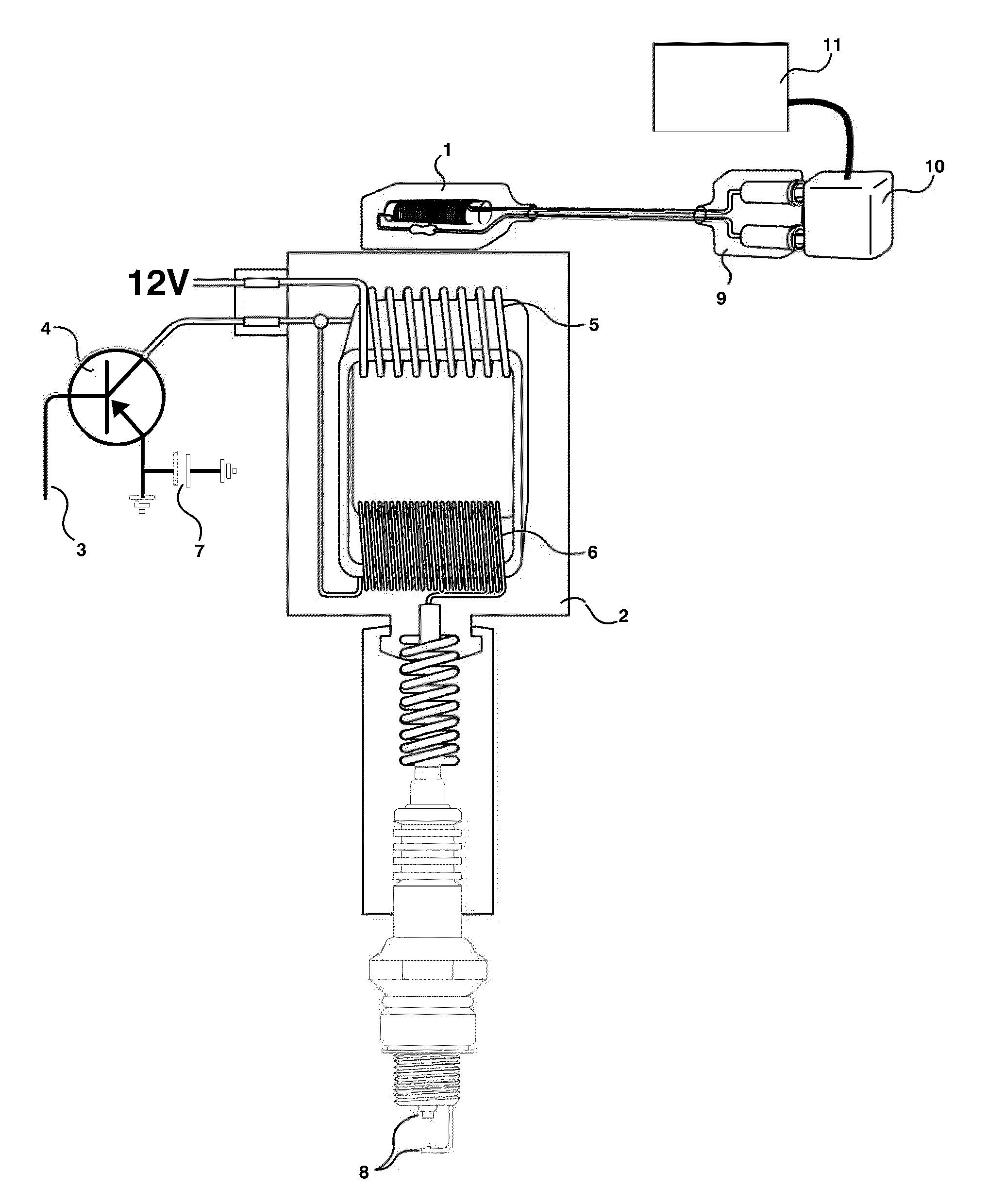
[0030]FIG. 5 shows the ignition pickup of the best mode contemplated by the inventors of the Universal Automotive Ignition Pickup Assembly according to the concepts of the present invention. The ignition pickup is comprised of a conductor 1 that is wound around a magnetizable center core 2. The preferred conductor is made of copper and is wound to form a coil consisting of many tight turns of winding. These windings will be constructed so the diameters of the turns are as large as possible. The space confinement that the ignition pickup will need to fit into in order to attach to various ignition coils will set the maximum diameter of the winding. The preferred center core is made of ferrite and is constructed in the format of a rod. The rod is as long and thick as possible. Again the space confinements that the pickup will need to fit into in order to attach to various ignition coils will set the maximum rod length and diameter. The preferred wrap of conductive wire around the magn...


PUM


Abstract

The present invention is a Universal Automotive Ignition Pickup Assembly that produces an ignition secondary voltage waveform that can be monitored by an oscilloscope or microprocessor. This is accomplished with a sensing probe that can be capacitive coupled; inductively coupled; or capacitive and inductively coupled at the same time. Due to the ability of a pickup to be capacitive and inductive at the same time, the ignition voltage waveforms are clear and concise from secondary ignition wires to a multitude of different ignition coil types.

Description

FIELD OF THE INVENTION[0001]An automotive capacitive inductive ignition pickup assembly that produces a voltage output signal which is read by a diagnostic oscilloscope or microprocessor. This ignition voltage signal is produced by the capacitive inductive pickup assembly being aligned to the electromagnetic field of a step-up transformer and having this field produce induction in the pickup assembly; or having the pickup assembly capacitive coupled to the secondary ignition wire during high voltage discharge. In either instance a voltage signal that mirrors the step up transformer secondary ignition voltage is produced within the capacitive inductive pickup assembly that is connected with two parallel conductive wires that are isolated from the step up transformer circuits; one being of a high potential; and one being of a low potential; to the diagnostic oscilloscope or microprocessor.DESCRIPTION OF PRIOR ART[0002]In a patent by Capek; U.S. Pat. No. 3,959,725; This disclosure show...

Claims


Application Information

Patent Timeline
IPC IPC(8): F02P17/00
CPCF02P17/12F02P2017/006F02P2017/003
Inventor THOMPSON, BERNIE C.PEDERSON, NEAL R.
Owner THOMPSON BERNIE C
Learn More