
Method and Apparatus for Facilitating Relay Node Communications

a relay node and communication technology, applied in the field of relay nodes and relays, can solve the problems of donor cells, wireless networks, and wireless networks, and achieve the effects of reducing backoff delay periods

Active Publication Date: 2012-04-05
NOKIA TECHNOLOGLES OY
View PDF21 Cites 121 Cited by
  • Summary
  • Abstract
  • Description
  • Claims
  • Application Information

AI Technical Summary

Benefits of technology

[0006]According to various example embodiments, priority access schemes for relay nodes, as described above and generally herein, enable reliable connection establishment between relay nodes and donor cells. Further, example embodiments expedite random access procedures over the backhaul link, once a UE succeeds in the random access procedure over the access link. Additionally, example embodiments alleviate the negative impact to multiple UEs accessing one relay node.
[0007]Although the example embodiments described above and generally herein may be described separately, one of skill in the art would appreciate that combinations of the example embodiments are also contemplated. For example, in accordance with an example embodiment, a higher transmission power for access preambles may be employed together with shorter backoff delay periods for relay nodes.

Problems solved by technology

Some wireless networks can be increasingly susceptible to degraded performance under particular conditions.
For example, a wireless network that employs a relay node to support communications between user equipment (UE), also referred to as a user device (e.g., a mobile terminal), and a donor cell (e.g., base station) can be susceptible to degraded performance when issues arise with respect to the communications link between the relay node and the donor cell, which, in some instances, may be referred to as the backhaul link.
In this and other instances, the overall quality of service of the system may be diminished, if the connection between the relay node and the donor cell is negatively impacted.

Method used


Image

  • Method and Apparatus for Facilitating Relay Node Communications
  • Method and Apparatus for Facilitating Relay Node Communications
  • Method and Apparatus for Facilitating Relay Node Communications

Examples


Embodiment Construction

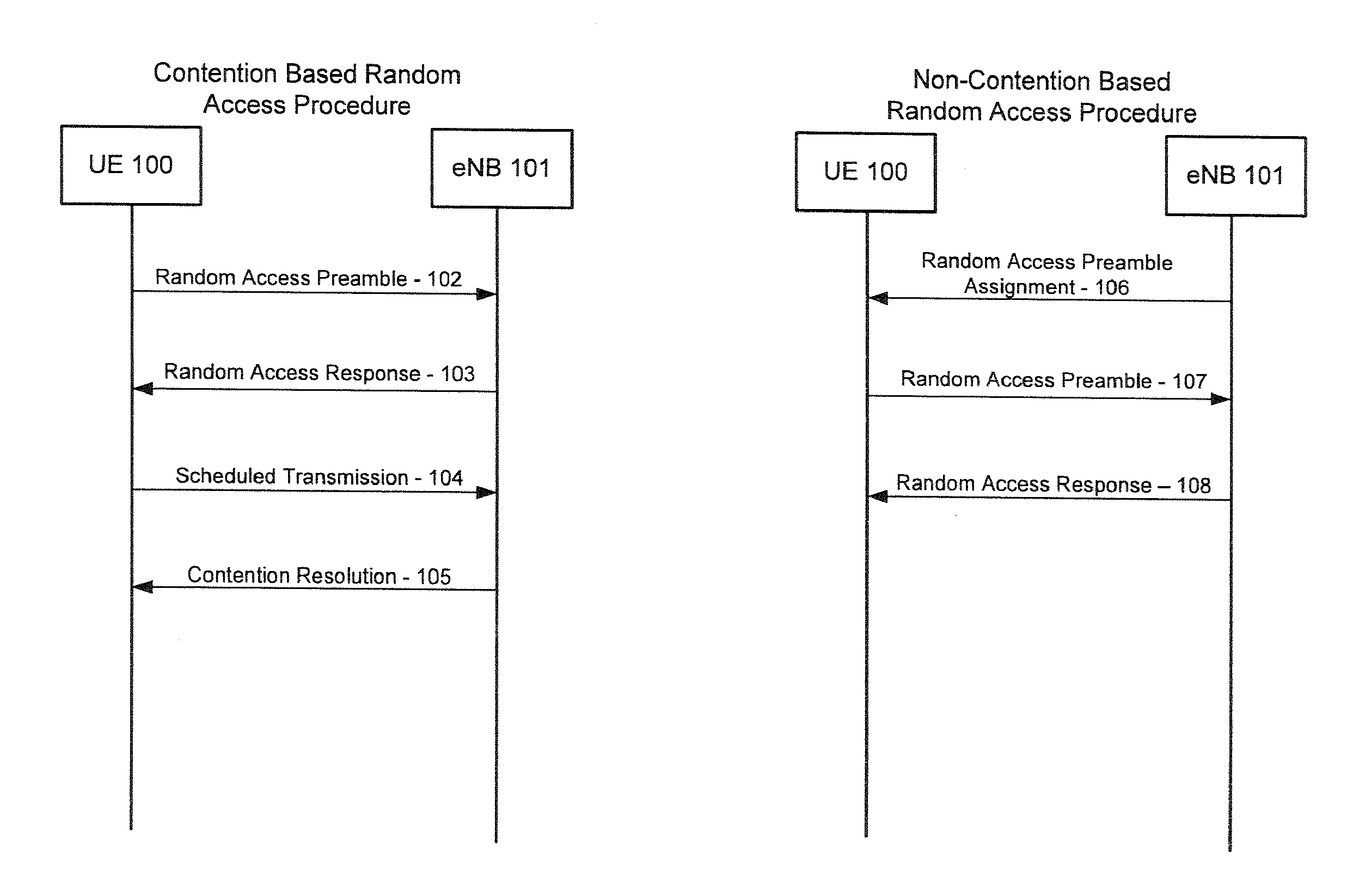
[0034]Example embodiments of the present invention will now be described more fully hereinafter with reference to the accompanying drawings, in which some, but not all embodiments of the invention are shown. Indeed, the invention may be embodied in many different forms and should not be construed as limited to the embodiments set forth herein; rather, these embodiments are provided so that this disclosure will satisfy applicable legal requirements. Like reference numerals refer to like elements throughout. The terms “data,”“content,”“information,” and similar terms may be used interchangeably, according to some example embodiments of the present invention, to refer to data capable of being transmitted, received, operated on, and / or stored.

[0035]As further described herein, various example embodiments of the present invention provide access priority to a relay node. Access priority may be provided in accordance with any number of message and session establishment techniques. In some ...


PUM


Abstract

Various methods for providing relay node priority are provided. One example method includes generating a relay node access message for initiating an access procedure to establish a connection between a relay node and a donor cell. The relay node access message may be generated in accordance with an access priority scheme. The access priority scheme may be defined such that a higher priority is allocated to the relay node access message than a user device access message for initiating the access procedure to establish a direct connection between the user device and the donor cell. The example method may also include providing for transmission of the relay node access message in accordance with the access priority scheme. Similar and related example methods and example apparatuses are also provided.

Description

TECHNICAL FIELD[0001]Embodiments of the present invention relate generally to mechanisms that support wireless communications, and, more particularly, relate to a method and apparatus for establishing a connection, such as a connection via a backhaul link of a relay node.BACKGROUND[0002]The modern communications era has brought about a tremendous expansion of wireless networks. Various types of networking technologies have been developed resulting in an unprecedented expansion of computing networks, telephony networks, and the like, fueled by consumer demand. Wireless and mobile networking technologies have addressed related consumer demands, while providing more flexibility and immediacy of information transfer.[0003]As users become increasingly dependant upon wireless networks for business and personal needs, the desire for faster and more widely accessible wireless communications increases. In some instances, wireless networks may employ various techniques, such as hardware or so...

Claims


Application Information

Patent Timeline
IPC IPC(8): H04B7/14H04W4/00H04L67/00
CPCH04W74/0875H04L12/4625H04W74/0833H04W84/047
Inventor DALSGAARD, LARSDU, LEISEBIRE, BENOIST PIERRE
Owner NOKIA TECHNOLOGLES OY
Learn More