Power generation system and power generating unit

Active Publication Date: 2012-04-12
PANASONIC INTELLECTUAL PROPERTY MANAGEMENT CO LTD
View PDF9 Cites 22 Cited by
  • Summary
  • Abstract
  • Description
  • Claims
  • Application Information

AI Technical Summary

Benefits of technology

[0021]A power generation system according to the present invention can transmit power wirelessly. Thus, according to the present invention, the cost of installing the power generating device can be reduced and the job of replacing a deteriorated part of the power generating device can get done more easily. In addition, when RF energies supplied from multiple power generating units are combined together, the phase difference between those R

Problems solved by technology

However, as that apparatus uses the same resonance method for the two resonators, the voltage is not increased while the energy is transferred.
This is also an effect that would never have been eas

Method used


Image

  • Power generation system and power generating unit
  • Power generation system and power generating unit
  • Power generation system and power generating unit

Examples


embodiment 1

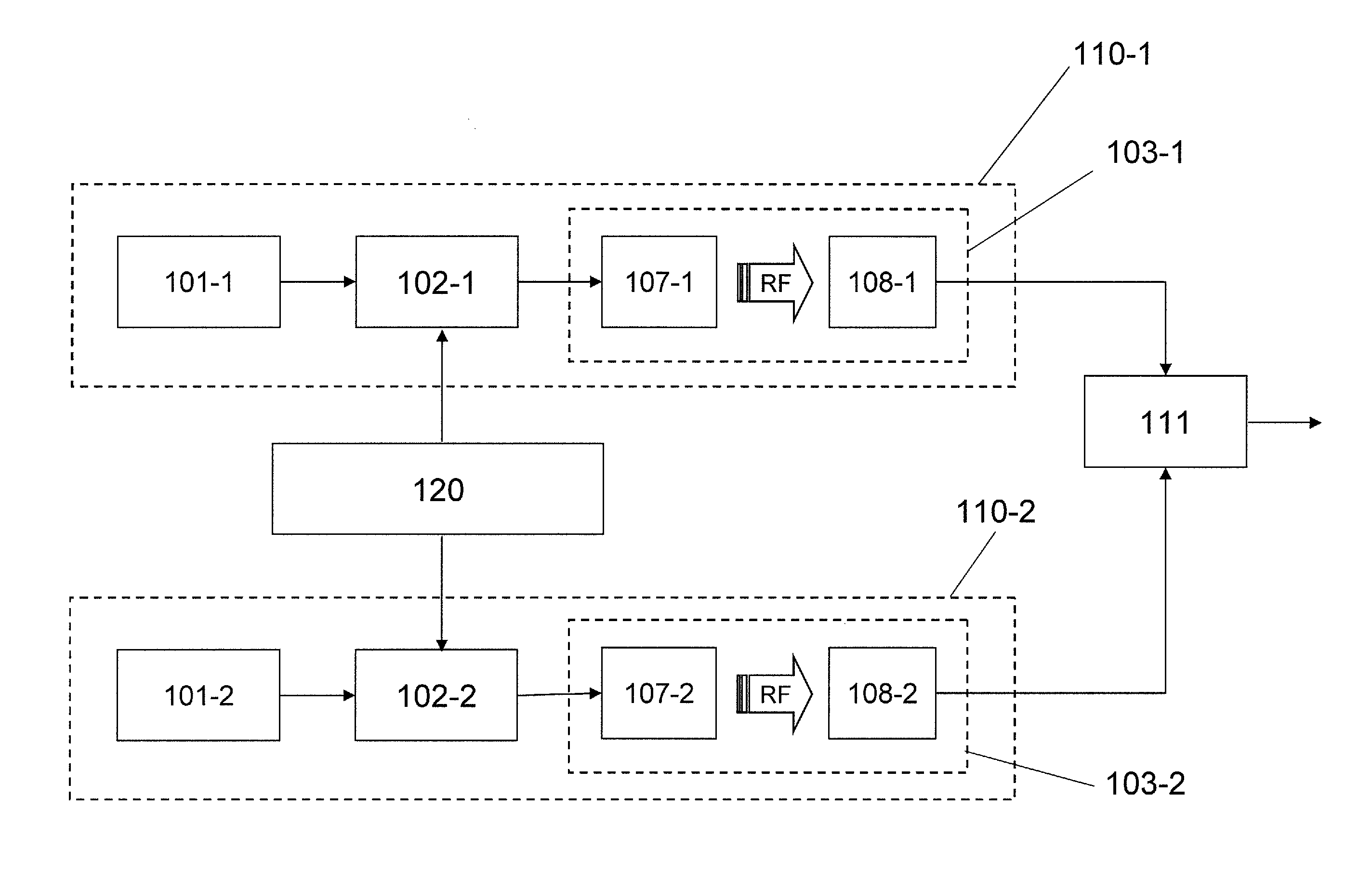
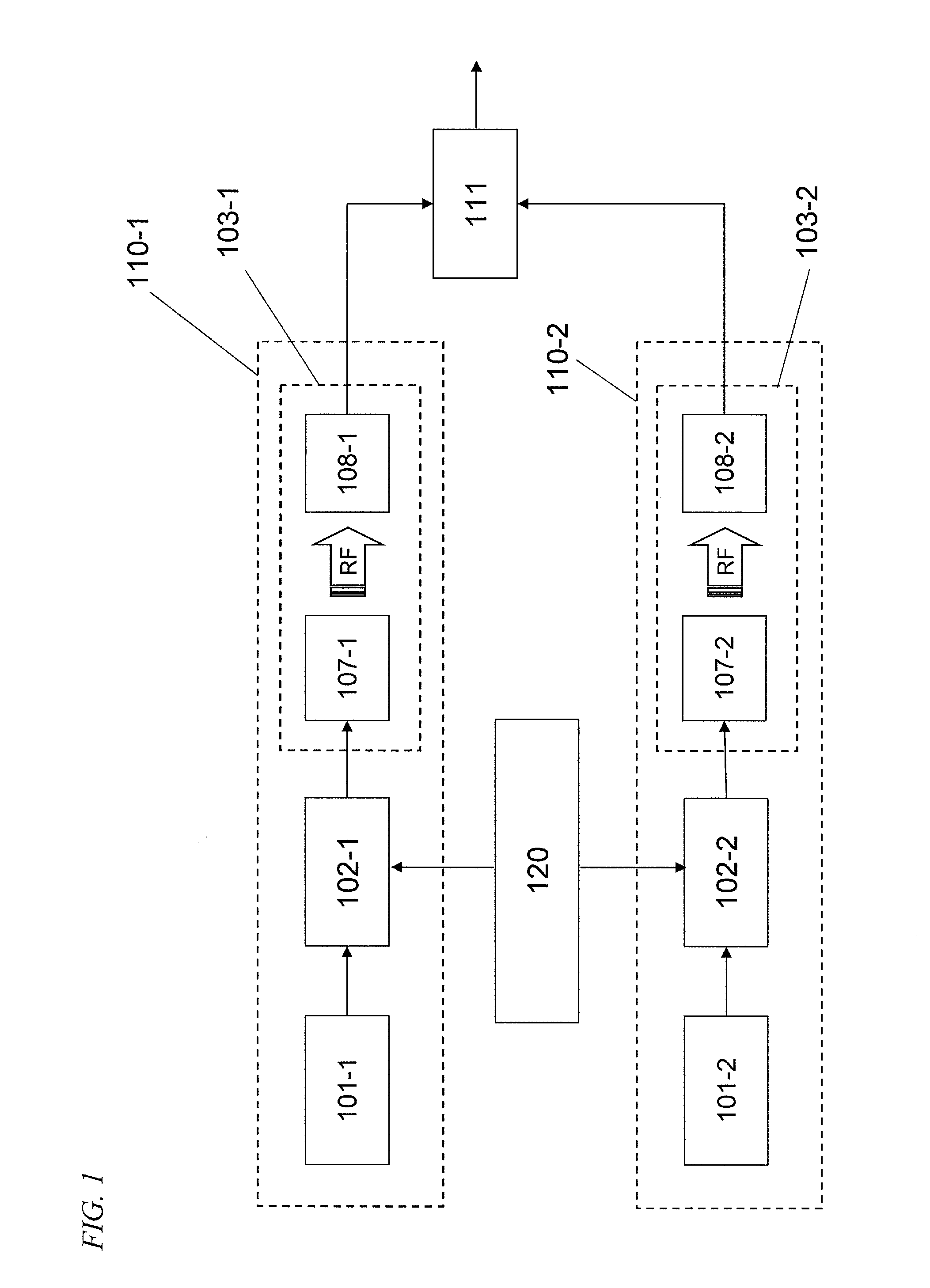
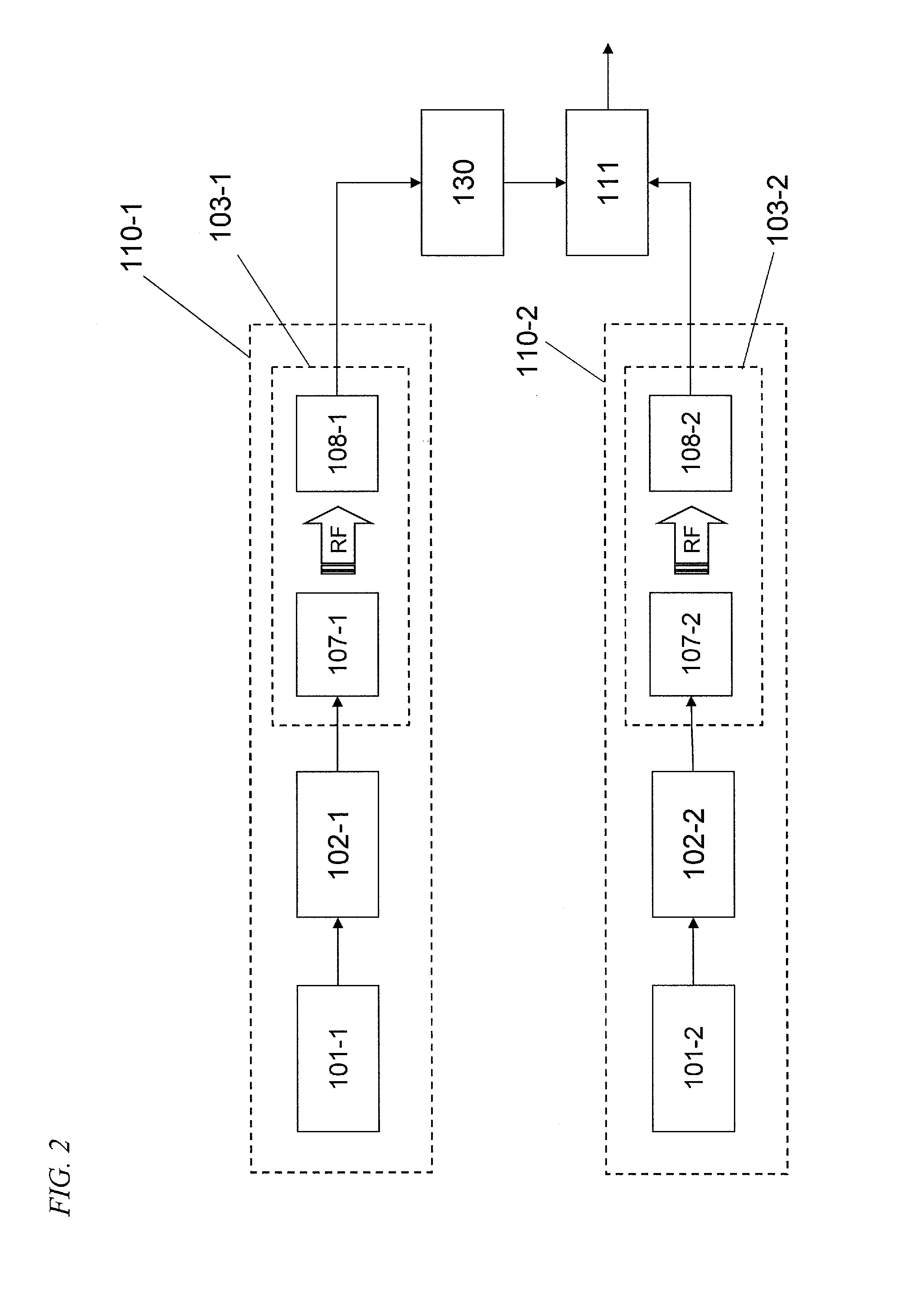
[0052]First of all, a First Specific Preferred Embodiment of the present invention will be described with reference to FIGS. 3 through 8. FIG. 3 illustrates an overall arrangement for a power generation system as a first preferred embodiment of the present invention. The power generation system of this preferred embodiment includes: a number of power generating units 110-1, . . . and 110-n, each of which converts the solar energy into RF energy and transmits the RF energy; a combining section 111 that combines together the respective RF energies supplied from those power generating units and outputs the combined RF energy; and a power converting section 112 that converts the combined RF energy obtained by the combining section 111 into either DC energy or AC energy with a lower frequency than the RF energy and then outputs the converted DC or AC energy to a load (such as an electronic device) or a utility grid.

[0053]Each power generating unit 110 includes: a power generating device ...

embodiment 2

[0106]Next, a second preferred embodiment of the present invention will be described with reference to FIG. 9.

[0107]The power generation system of this preferred embodiment can match the respective impedances of its circuit blocks to each other according to a variation in the output impedance of the power generating device 101, which is a major difference from the power generation system of the first preferred embodiment described above. Thus, the following description of this second preferred embodiment will be focused on the differences from the power generation system of the first preferred embodiment and their common features will not be described all over again to avoid redundancies.

[0108]If the power generating device 101 is a solar cell, the output impedance of the power generating device 101 may vary according to some environmental condition such as the intensity of the sunlight that irradiates the cell and the temperature of the cell itself. For that reason, if a fixed load...


PUM


Abstract

The power generation system includes first and second power generating units, each of which converts DC energy into RF energy and transmits the power wirelessly, a combining section, which combines the respective outputs of the power generating units together, and an oscillation phase control section, which reduces the phase difference between the RF energies supplied from the two power generating units and. The oscillation phase control section controls a phase difference between the RF energies supplied from the oscillators and belonging to the first and second power generating units and, respectively, so that first and second RF energies supplied from the first and second power generating units and are in phase with each other when combined together by the combining section.

Description

[0001]This application claims priority under 35 USC §119(e) to U.S. Provisional Application No. 61 / 391,286 filed on Oct. 8, 2010, the entire contents of which are incorporated herein by reference.BACKGROUND OF THE INVENTION[0002]1. Field of the Invention[0003]The present invention relates to a power generation system and power generating unit for transferring energy wirelessly by magnetic resonant coupling.[0004]2. Description of the Related Art[0005]To avoid exhausting valuable natural resources and to cope with the global warming effect that has been growing year by year, people have been paying more and more attention to solar power generation that never releases harmful carbon dioxide. In fact, a power plant for generating a lot of electric power by installing a huge number of solar power generators (i.e., so-called “solar cells”, which will be sometimes simply referred to herein as “cells”) in a wide area has become a reality. In most cases, solar power generators for general c...

Claims


Application Information

Patent Timeline
IPC IPC(8): H02J17/00
CPCH02J17/00H02J50/12H02J50/20H02J50/402H02J50/005
Inventor YAMAMOTO, HIROSHIKANNO, HIROSHI
Owner PANASONIC INTELLECTUAL PROPERTY MANAGEMENT CO LTD
Why Eureka
Try Eureka