

Capacitive electromechanical transducer
a technology of electromechanical transducer and capacitive electrode, which is applied in the direction of electrostatic generator/motor, mechanical vibration separation, electrostatic motor, etc., can solve the problem of the difference in the pressure between the electrodes and exceed the restoration for
- Summary
- Abstract
- Description
- Claims
- Application Information
AI Technical Summary
Benefits of technology
Problems solved by technology
Method used
Image

Examples
first embodiment
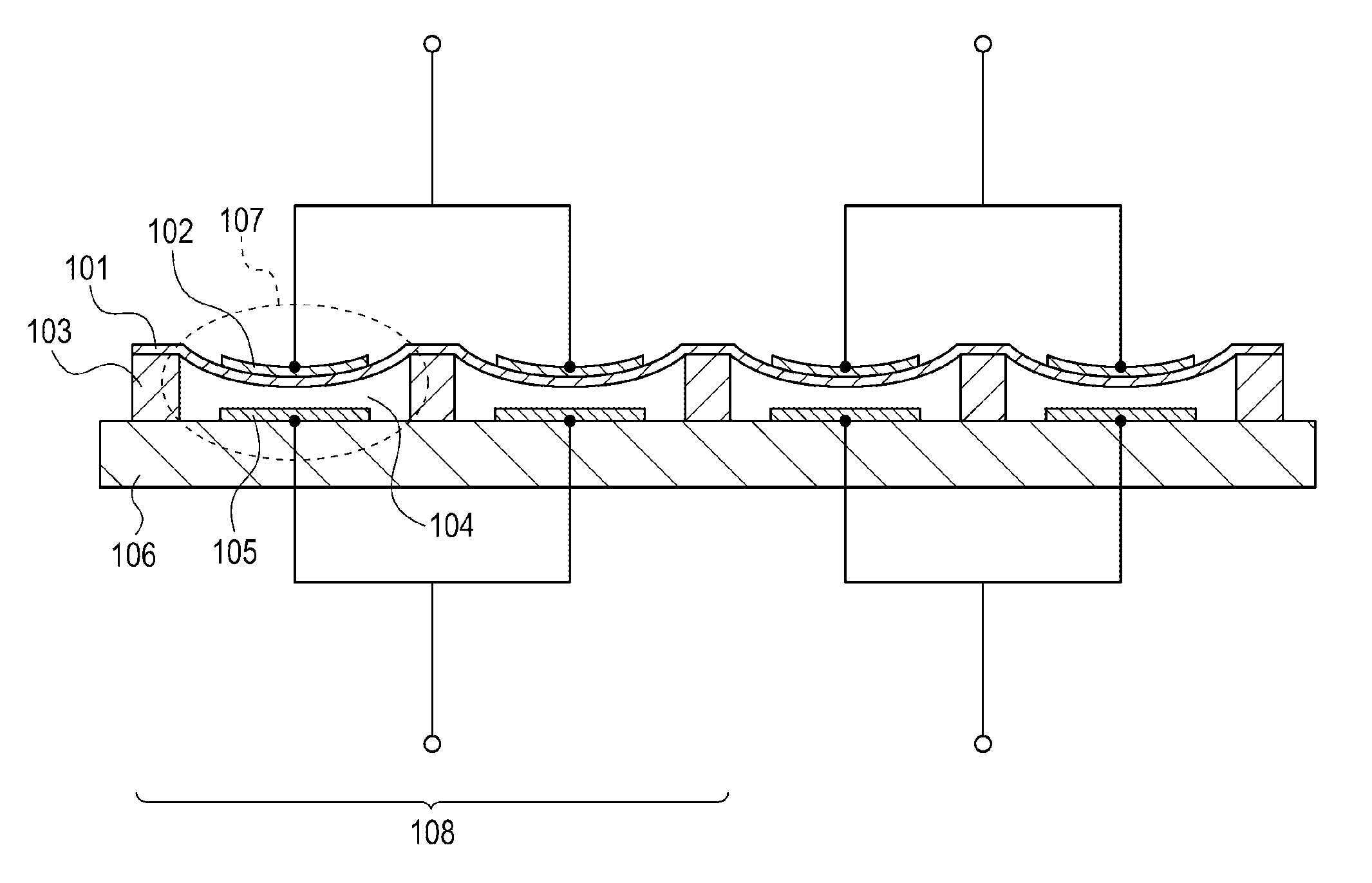
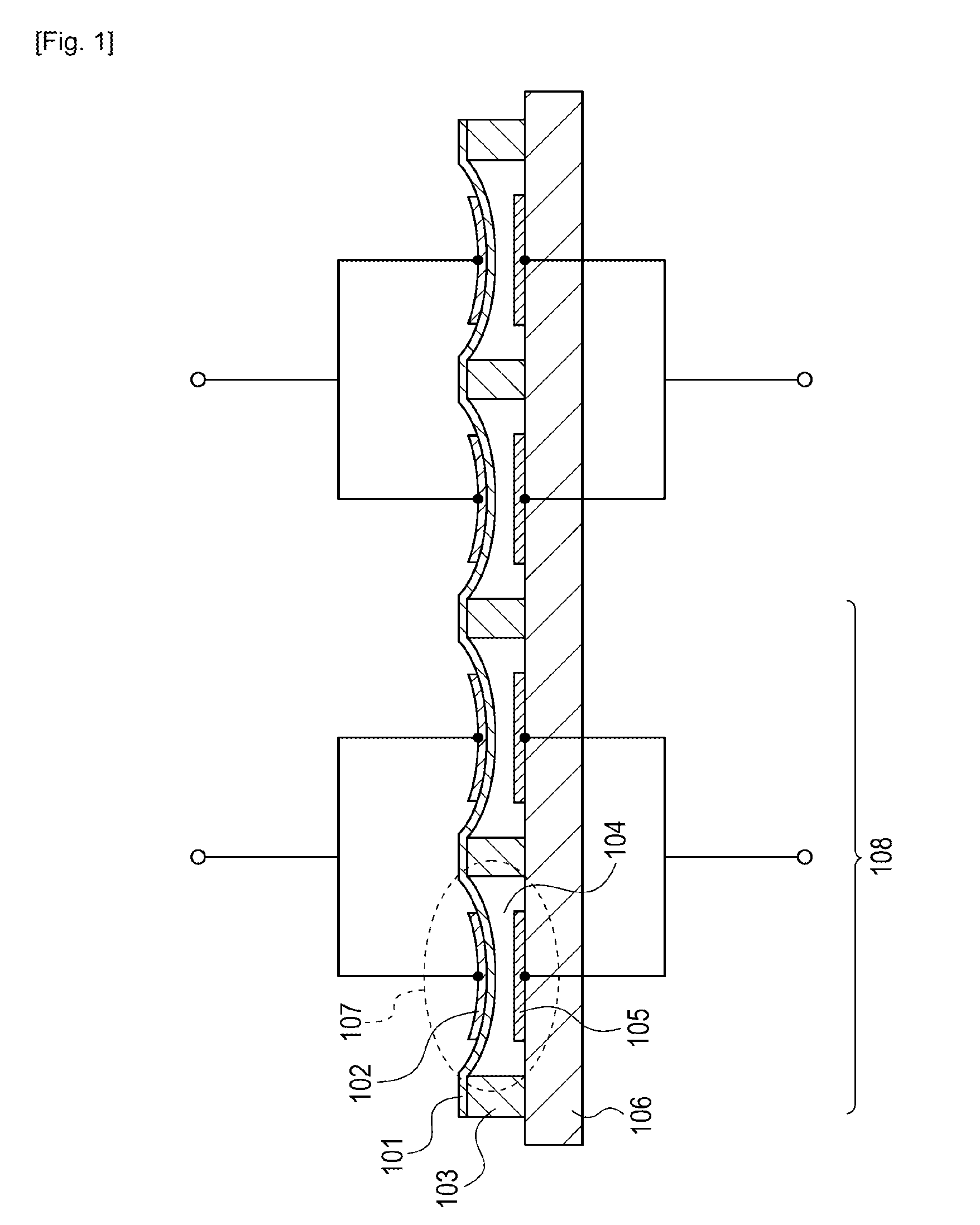
[0021]FIG. 1 is a schematic cross-sectional view of an electromechanical transducer according to a first embodiment of the present invention. The first electrode is called an upper electrode and the second electrode is called a lower electrode in the embodiments of the present invention. A vibrating membrane 101 on which an upper electrode 102 is formed is supported by a supporter 103 formed on a substrate 106. The vibrating membrane 101 vibrates along with the upper electrode 102. A lower electrode 105 is formed on the substrate 106 at a position that is opposed to the upper electrode 102 on the vibrating membrane 101 with a gap 104 sandwiched therebetween. A composition including the upper electrode and the lower electrode, which are opposed to each other with the gap 104 sandwiched therebetween, is called a cell 107 in the embodiments of the present invention. An element 108 includes at least one cell 107. Specifically, the element 108 is a composition including one cell 107 or i...
second embodiment
[0030]A second embodiment of the present invention will now be described with reference to FIG. 3. The second embodiment concerns the configuration of wiring lines from the upper electrodes and the lower electrodes. The remaining configuration in the second embodiment is the same as in the first embodiment.
[0031]FIG. 3 is a cross-sectional view of an electromechanical transducer according to the second embodiment of the present invention. A through wiring line substrate 303 includes two kinds of wiring lines passing through the substrate: a lower-electrode through wiring line 301 (second-electrode through wiring line) and an upper-electrode through wiring line 302 (first-electrode through wiring line). All the lower electrodes 105 in each element are connected to one lower-electrode through wiring line 301. The lower-electrode through wiring line 301 extends from the face of the through wiring line substrate 303 toward the lower electrodes to the face thereof toward a printed circui...
third embodiment
[0034]A third embodiment of the present invention will now be described with reference to FIG. 4. The third embodiment is characterized in that a control-signal generating unit is provided to instruct a DC voltage to be applied to the DC voltage applying unit 201. The remaining configuration in the third embodiment is the same as in either of the first and second embodiments.
[0035]FIG. 4 illustrates an example of the configuration of an electromechanical transducer according to the third embodiment of the present invention. A vibrating-membrane state detecting unit 401 detects the amount of deflection of the vibrating membranes 101 (this is equivalent to detection of the distance between the upper electrodes and the corresponding lower electrodes). Since the magnitude of a current detected at each lower electrode is in reverse proportion to the square of the distance between the upper electrode and the lower electrode (hereinafter simply referred to as an electrode distance) and is ...
PUM
 Abstract
Description
Claims
Application Information