
Illumination system and method for controlling the same

Active Publication Date: 2012-04-12
SEOUL SEMICONDUCTOR
View PDF11 Cites 16 Cited by
  • Summary
  • Abstract
  • Description
  • Claims
  • Application Information

AI Technical Summary

Benefits of technology

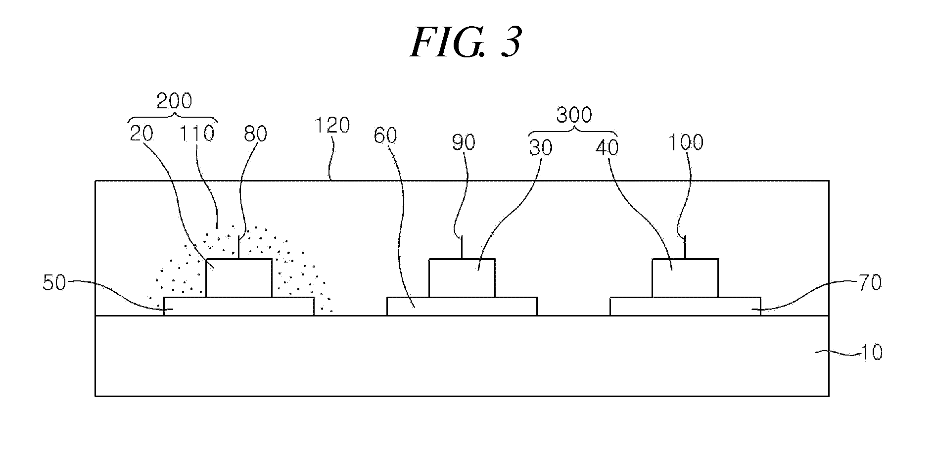
[0009]The present invention is conceived to solve the aforementioned problems. An object of the present invention is to provide a light emitting apparatus wherein a plurality of light emitting portions are formed in a single package to implement the light with a variety of light emitting intensities and color temperatures, thereby being applied to a desired environment and use and enhancing the efficiency of spaces and cost.
[0017]The present invention has an advantage in that a plurality of light emitting portions are formed in a single package to implement white the light with a variety of light emitting intensities and color temperatures, thereby being variously applied to a desired environment and use. Furthermore, there is an effect in that light emitting portions, each of which constitutes a separate package in a prior art, are formed in a single package, thereby reducing the cumbersomeness in a process, enhancing the space efficiency, and reducing the costs.
[0018]And, in accordance with the present invention, it is possible to provide an illumination system capable of adjusting light emitting intensities and color temperatures according to ambient environment information or preset information based on user's individual preference. Accordingly, it becomes possible to provide an individual user with optimum illumination, thus maximizing user's satisfaction with the illumination system.

Problems solved by technology

However, since a conventional light emitting apparatus maintains a certain light emitting intensity and color temperature, it is cumbersome that a light emitting apparatus should be individually manufactured depending on its use.
Therefore, there is a s disadvantage in that a light emitting apparatus is increased in manufacturing cost and occupies a large mounting space.

Method used


Image

  • Illumination system and method for controlling the same
  • Illumination system and method for controlling the same
  • Illumination system and method for controlling the same

Examples


first embodiment

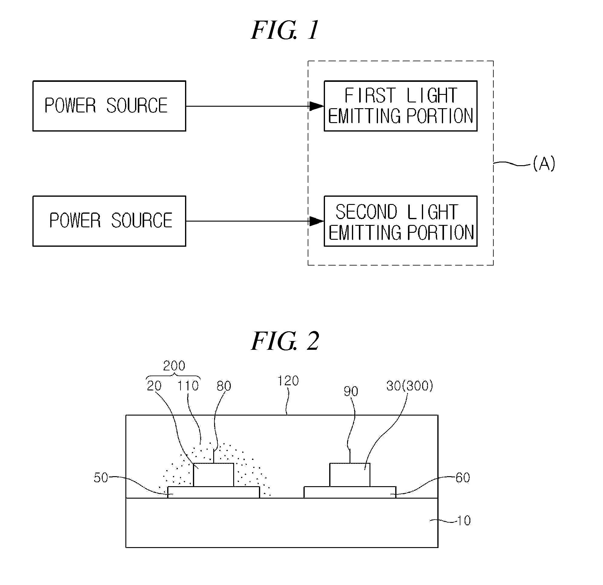
[0040]FIG. 1 is a block diagram conceptually illustrating a first embodiment according to the present invention.

[0041]Referring to FIG. 1, a light emitting apparatus is characterized in that it comprises a first light emitting portion emitting white light with a color temperature of 5700K or more and a second light emitting portion capable of changing the color temperature of the white light emitted from the first light emitting portion, wherein the first and second light emitting portions can be driven independently of each other.

[0042]The first light emitting portion emits white light with a color temperature of 5700K or more, i.e., white light known as daylight. To this end, the first light emitting portion may comprise a light emitting diode chip emitting blue light and a phosphor for emitting yellow light. That is, the white light is implemented through the mixture of blue light emitted from the light emitting diode chip and yellow light wavelength-converted by the phosphor.

[00...


PUM


Abstract

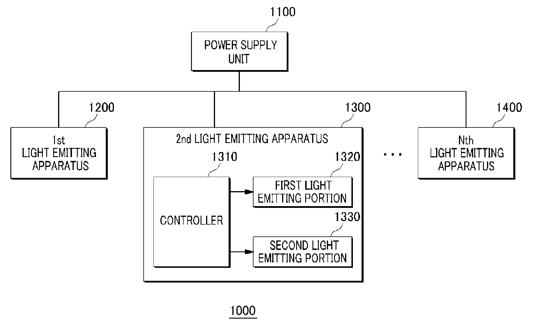
An illumination system includes a power supply unit; and a light emitting apparatus driven by power supplied from the power supply unit. The light emitting apparatus includes: a first light emitting portion and a second light emitting portion configured to be independently driven to emit output light; and a controller configured to control a color temperature or a luminous flux of the output light by controlling operations of the first and second light emitting portions. The controller is configured to control an output color temperature of the output light according to color temperature control data for controlling an output color temperature of the second light emitting portion or control a luminous flux of the output light according to luminous flux control data for controlling an output luminous flux of the first light emitting portion.

Description

CROSS-REFERENCE TO RELATED APPLICATIONS[0001]The present application is continuation-in-part of application Ser. No. 12 / 159,677 filed Dec. 28, 2006, entitled “LIGHT EMITTING APPARATUS”, which is the National Stage of International Application No. PCT / KR2006 / 005790, filed on Dec. 28, 2006, and claims priority from and the benefit of Korean Patent Application No. 10-2005-0135767, filed on Dec. 30, 2005, which are all hereby incorporated by reference for all purposes as if fully set forth herein.BACKGROUND OF THE INVENTION[0002]1. Field of the Invention[0003]The present invention relates to a light emitting apparatus, and more particularly, to a light emitting apparatus wherein a plurality of light emitting portions are formed in a single package to implement the light with a variety of light emitting intensities and color temperatures.[0004]2. Discussion of the Background[0005]A light emitting diode (LED) is an element in which minority carriers (electrons or holes) are produced usin...

Claims


Application Information

Patent Timeline
IPC IPC(8): H05B37/02H05B37/00H05B44/00
CPCH05B45/28H05B45/10
Inventor KIM, JAE JO
Owner SEOUL SEMICONDUCTOR
Learn More