CVT Pulley With Engineered Surface

a technology of engineered surface and pulley, which is applied in the direction of mechanical equipment, manufacturing tools, hoisting equipment, etc., can solve the problems of inability to produce engineered surface, inability to change the friction coefficient between the belt and the pulley surface, and inability to precisely achieve engineered surface, etc., to achieve enhanced oil retention and desirable hydrodynamic film characteristics, reduce surface wear, and reduce the effect of surface wear

Active Publication Date: 2012-04-12
GM GLOBAL TECH OPERATIONS LLC
View PDF6 Cites 18 Cited by
  • Summary
  • Abstract
  • Description
  • Claims
  • Application Information

AI Technical Summary

Benefits of technology

[0007]An advantage of an embodiment is that the consistency of the engineered surface roughness of the CVT pulleys allows for a reduction in the wear of the pulley surfaces while still providing the desired friction to meet torque demands on the transmission. The micro-machined slots created in the surface by the femto-pulsed laser can enhance oil retention and desirable hydrodynamic film characteristics of the pulley surfaces that allow for the desired torque transfer capability while reducing the surface wear.

Problems solved by technology

Over time, the micro-slippage causes a surface texture depth reduction due to mixed boundary lubrication conditions, which, with usage, may change the coefficient of friction between the belt and the pulley surface.
While these mechanical methods of creating surface roughness produce a desired average, the roughness is random and not consistent, so the roughness just meets an overall average.
The actual peak to valley height that determines the average roughness is not consistent throughout the treated surface area, thus a precise, engineered surface is not produced.

Method used


Image

  • CVT Pulley With Engineered Surface
  • CVT Pulley With Engineered Surface

Examples


Embodiment Construction

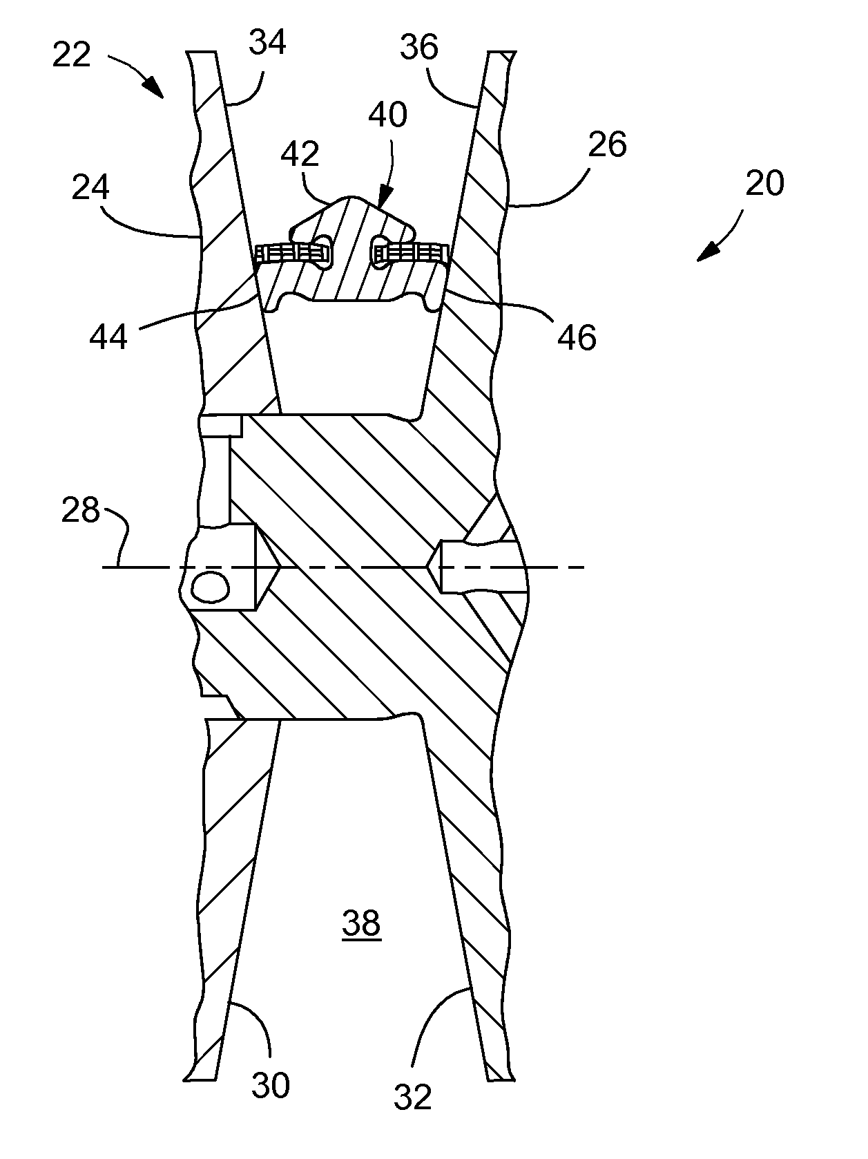
[0011]Referring to FIG. 1, a portion of a continuously variable transmission (CVT), indicated generally at 20, is shown. The CVT 20 includes a pulley 22 having a first pulley half 24 facing a second pulley half 26. The second pulley half 26 is axially fixed relative to an axis of rotation 28, while the first pulley half 24 is axially slidable toward and away from the second half 26. This axial sliding motion may be provided using hydraulic, electronic or other means. The pulley halves 24, 26 may be made of, for example, a medium carbon steel—although other materials may be used instead, if so desired.

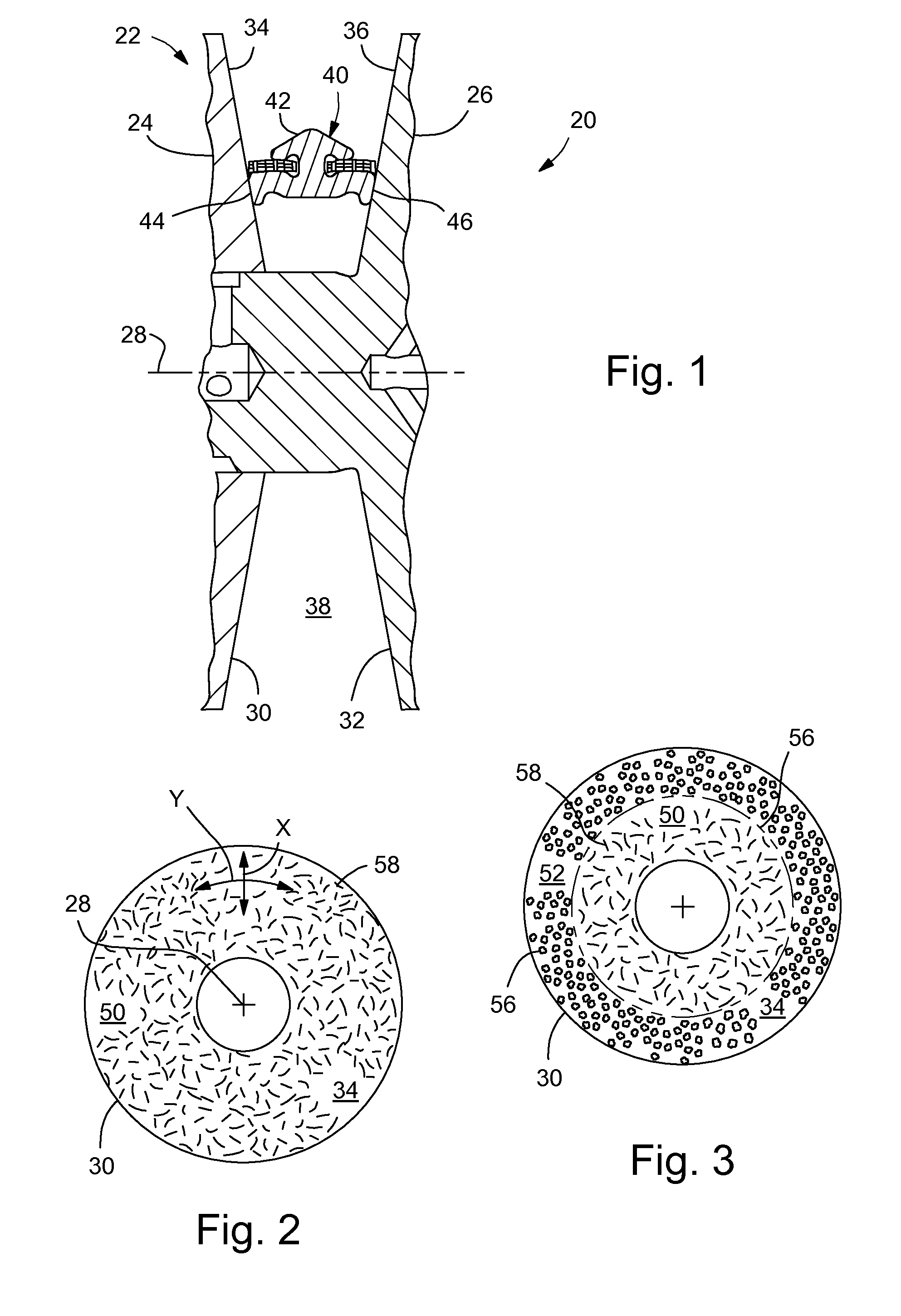
[0012]Each of the pulley halves 24, 26 has a truncated conical portion 30, 32, respectively, with outer surfaces 34, 36, respectively, that face each other. The outer surfaces 34, 36 are sloped relative to the axis 28 and form a resizable recess 38 within which is mounted a belt 40 (the belt only shown in the top half of the pulley). As the first pulley half 24 slides toward and away fr...


PUM

PropertyMeasurementUnit
transmissionaaaaaaaaaa
roughnessaaaaaaaaaa
areaaaaaaaaaaa

Abstract

A pulley for a continuously variable transmission and a method of creating an engineered surface on an outer surface of a pulley of a continuously variable transmission, with the engineered surface engaging with a belt or chain of the continuously variable transmission. The method comprising the steps of: determining an actual engineered roughness (Rpk) on the outer surface needed to obtain a predetermined friction between the engineered surface and the belt or chain; and etching microgrooves in at least a portion of the outer surface to create the engineered surface by employing a laser to etch the microgrooves, the microgrooves being formed to a depth that produces the actual engineered roughness (Rpk).

Description

BACKGROUND OF INVENTION[0001]The present invention relates generally to a continuously variable transmission (CVT), and more particularly to the surfaces on a pulley of the CVT.[0002]Some continuously variable transmissions (CVT) use pulley assemblies with one truncated conical member that is movable relative to another truncated conical member, with a belt or chain mounted between them. The ratio of the input pulley to the output pulley is adjusted by varying the spacing between the conical members. The torque is transferred via friction between the conical members and the belt or chain.[0003]In vehicles having engines with higher power output, the CVT needs to have a higher torque capacity. The higher torque capacity is achieved, in part, by maintaining a high frictional engagement between the belt / chain and the conical members. This must be achieved, however, while still providing adequate wear resistance of the conical surfaces to assure long term durability of the transmission....

Claims


Application Information

Patent Timeline
Patent Type & Authority Applications(United States)
IPC IPC(8): F16H55/56B23K26/36
CPCB23K26/0084C23C14/028F16H61/66272F16H55/38F16H55/56C23C14/0641B23K26/355
Inventor BRIGGS, ROGER L.KRAMER, MARTIN S.BUFFA, RONALD P.WERNER, MATTHEW P.
Owner GM GLOBAL TECH OPERATIONS LLC
Why Eureka
Try Eureka