As a result many of the
microprocessor resources may be under utilized, as there is not a one-to-one match between the application algorithms and hardware resources.
In addition, many calculations require the transfer and
temporary storage of intermediate results, which further consumes
processing time and power.
Due to their sequential
processing, microprocessors and hence related
software approaches to parallelism tend to be much slower and inefficient, especially when implementing
Digital Signal Processing (DSP) intensive applications.
Nonetheless, such common
bus schemes are inefficient and provide data /
processing bottlenecks.
In addition, such arrays have the
disadvantage that each homogeneous
processing element needs to be quite complex (implement many type of arithmetic and logic functions) as it may be required to implement one of many functions depending on the
algorithm to be implemented.
It also means that the processing array is synchronous and any
delay in one thread will interfere with the processing of other non-related threads.
Due to the global
synchronous switching of data and array elements the processing of independent threads is limited.
This type of processing architecture tends to be very unwieldy to implement and program for.
However, if a VLIW
compiler cannot find enough parallel operations to fill all of the slots in an instruction, it must place explicit
NOP (no-operation) operations into the corresponding operation slots.
However, they have limited applications.
Another
disadvantage of array processors is that they are based on coarse-grained processing elements and as a consequence it is difficult to implement fine-grained logic functions.
Again, this limits the use of these devices.
This further complicates the issue, especially at design time as many different design tools e.g. separate compilers and simulators for the embedded cores and hardware resources are required to design and test any application.
The
disadvantage to this approach is that the DSP slices tend to target particular applications and hence FPGA manufacturers need to provide different versions of FPGAs to target these different applications.
Though these more complex FPGAs provide a high degree of user programmability they are not fully flexible.
Unfortunately, there are several disadvantages to using FPGAs when compared to alternatives, such as
Application Specific Integrated Circuits (ASICs).
Firstly, FPGAs tend to be much larger than their hardwired ASIC counterparts, consume more power and are more expensive.
Secondly, though they can be re-programmed, a large amount of memory is required to implement specific functions.
Another disadvantage of FPGAs is that there is a significant routing overhead required to interconnect all the fine-grained LUTs.
However, there is a major design conflict with test circuitry.
These approaches tend to be unwieldy (especially for large multi-dimensional arrays as they do not scale well), consume valuable
silicon real estate and can hinder thread processing due to delays required to implement thread synchronisation.
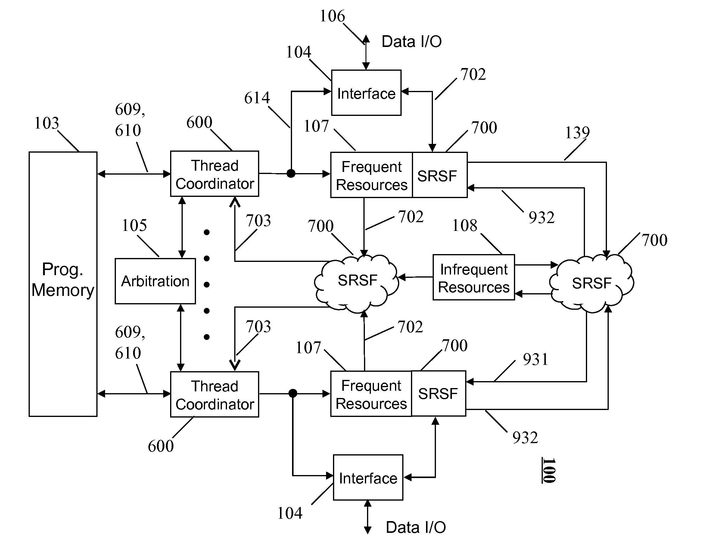
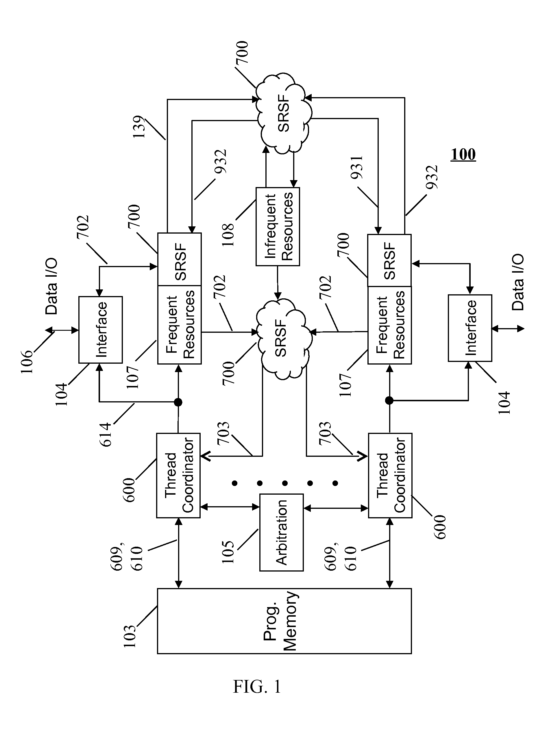
This then reduces the number of program memory and or cache accesses, which can be significant when large program loops are being executed.
Consequently, it would be a very inefficient use of
silicon real estate to provide these infrequent functions locally or in every processing element.
This situation could occur due to uneven or bursty data flows, for example when interrupts occur or data output varies when implementing a compression algorithm.

