
Exhaust line for a motor vehicle with a closed recovery cycle for exhaust gas heat energy, and associated control method

a technology of exhaust gas and heat energy recovery, which is applied in the field of recovery of energy in motor vehicle exhaust lines, can solve the problems of significant loss of heat energy recovery yield from exhaust gases, risk of unpriming the closed cycle for recovering heat energy, etc., and achieve the effect of improving yield

Inactive Publication Date: 2012-04-19
FAURECIA SYST DECHAPPEMENT
View PDF13 Cites 10 Cited by
  • Summary
  • Abstract
  • Description
  • Claims
  • Application Information

AI Technical Summary

Benefits of technology

[0007]The invention proposes an exhaust line in which recovery of the heat energy from the exhaust gases is carried out with a better yield.

Problems solved by technology

When little energy is available in the exhaust, i.e. when the power of the engine requested by the driver is low, there is a risk of unpriming the closed cycle for recovering heat energy.
Re-priming of the closed cycle is long, which causes a significant loss for the heat energy recovery yield from the exhaust gases.

Method used


Image

  • Exhaust line for a motor vehicle with a closed recovery cycle for exhaust gas heat energy, and associated  control method
  • Exhaust line for a motor vehicle with a closed recovery cycle for exhaust gas heat energy, and associated  control method
  • Exhaust line for a motor vehicle with a closed recovery cycle for exhaust gas heat energy, and associated  control method

Examples


Embodiment Construction

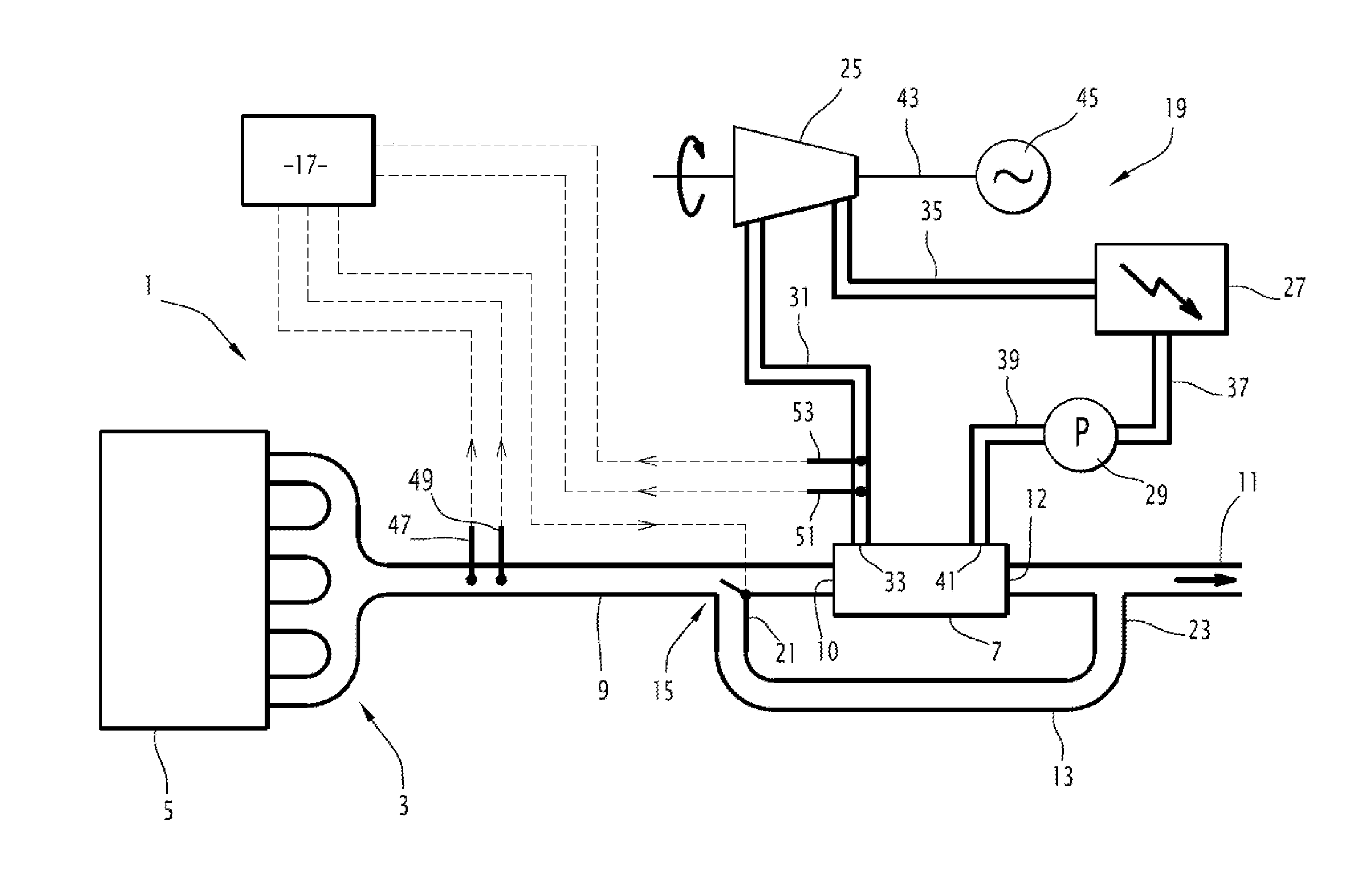
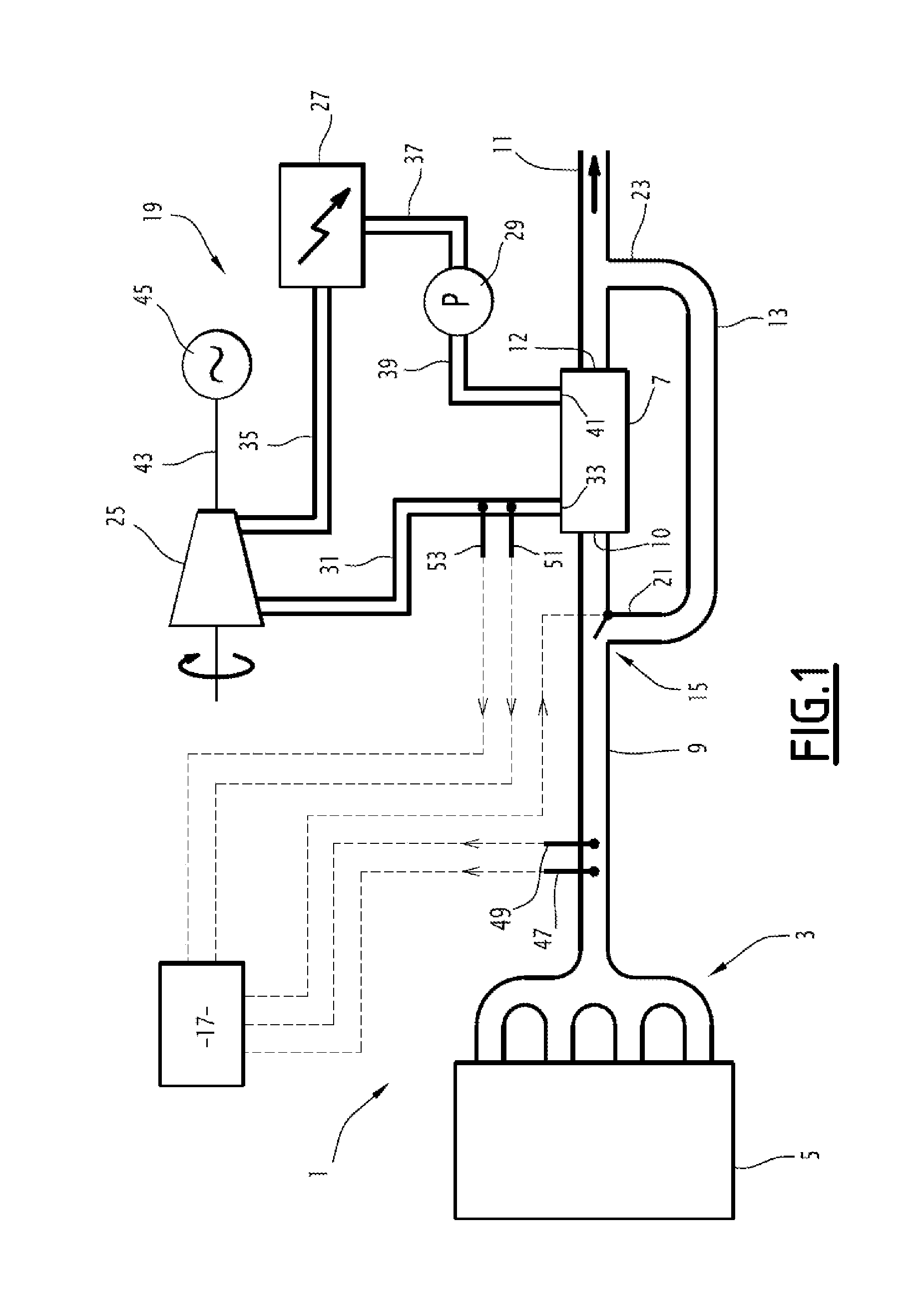
[0042]The exhaust line 1 illustrated in a simplified way in FIG. 1 includes:[0043]a manifold 3 provided for collecting the exhaust gases exiting from the combustion chambers of a heat engine 5 of the motor vehicle;[0044]a heat exchanger 7, having a first side for circulation of the exhaust gases and a second side for circulation of a heat exchange fluid;[0045]an upstream conduit 9 for circulation of the exhaust gases, and which connects the manifold 3 to an inlet 10 on the first side of the heat exchanger 7;[0046]a downstream conduit 11 for circulation of the exhaust gases, and which is connected to an outlet 12 of the first side of the heat exchanger 7;[0047]a bypass conduit 13 that connects a point of the upstream conduit 9 to a point of the downstream conduit 11 by bypassing the heat exchanger 7;[0048]a member 15 for selectively orienting the exhaust gases towards the heat exchanger 7 and / or towards the bypass conduit 13;[0049]a member 17 for controlling the orientation member 15...


PUM


Abstract

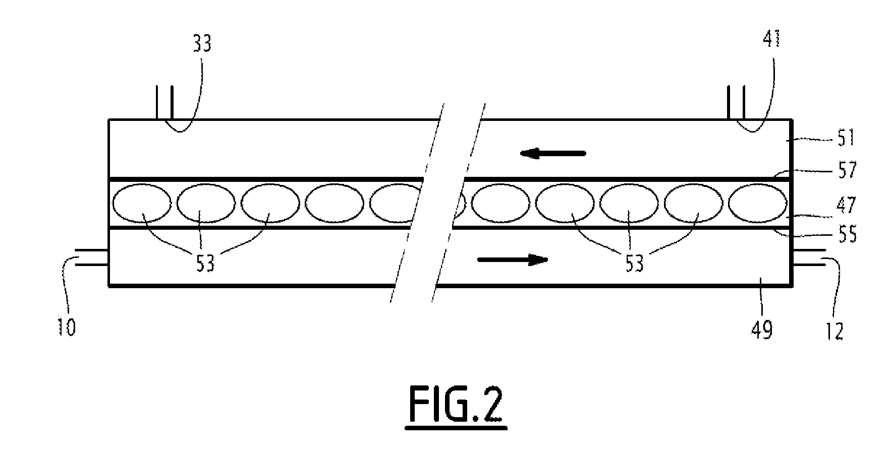
An exhaust line of a motor vehicle includes a heat exchanger having a first side for circulating the exhaust gases and a second side for circulating a heat exchange fluid, and a closed recovery cycle for one portion of the heat energy of the exhaust gases, in which said heat exchange fluid circulates, wherein the second side of the heat exchanger is inserted inside the closed cycle. The heat exchanger includes an intermediate wall interposed between the first and second sides of the heat exchanger. The intermediate wall comprises at least one closed cavity including a phase change material. The intermediate wall has a first exchange surface in thermal contact with the exhaust gases and a second exchange surface in thermal contact with the heat exchange fluid.

Description

RELATED APPLICATION[0001]This application is a United States National Phase Application of PCT Application No. PCT / FR2010 / 050545, filed on Mar. 25, 2010, which claims priority to French Application No. 09 51920, filed on Mar. 25, 2009.TECHNICAL FIELD[0002]The invention generally relates to the recovery of energy in motor vehicle exhaust lines.BACKGROUND OF THE INVENTION[0003]An exhaust line of a motor vehicle comprises: a heat exchanger having a first side for circulation of exhaust gases and a second side for circulation of a heat exchange fluid; and a closed cycle for recovering a portion of the heat energy of the exhaust gases, in which said heat exchange fluid circulates, the second side of the heat exchanger being inserted into the closed cycle.[0004]Such an exhaust line is known from US A-2006 / 0201153. In such an exhaust line, the means for recovering the heat energy of exhaust gases have no, or very little, thermal inertia.[0005]The energy recovered by the closed cycle is alm...

Claims


Application Information

Patent Timeline
IPC IPC(8): F01N5/02
CPCF01K23/065F01N5/02Y02T10/16Y02E60/145F28D20/02F01K13/02F28D21/0003F28D2020/0008Y02E60/14Y02T10/12
Inventor BARRIEU, EDOUARD
Owner FAURECIA SYST DECHAPPEMENT
Learn More