refrigerator

a technology of refrigerators and cooling devices, which is applied in the field of refrigerators, can solve the problems of leaking heat medium out of the system, and unable to fulfill the capability of cooling devices, and achieve the effect of simple and highly reliabl

Active Publication Date: 2012-04-19
KOBELCO COMPRESSORS CORP
View PDF9 Cites 4 Cited by
  • Summary
  • Abstract
  • Description
  • Claims
  • Application Information

AI Technical Summary

Benefits of technology

[0011]According to this structure, since the exhaust side of the screw expander and the discharge side of the screw compressor communicate with each other, the exhaust pressure of the screw expander and the discharge pressure of the screw compressor becomes the same to prevent the occurrence of flow of heat medium. Thus, the refrigerator of the present invention is inexpensive and has less frequency of failure and high maintenance property with a simplified structure without the need for providing shaft seal devices on the exhaust side of the screw expander and on the discharge side of the screw compressor.
[0017]According to this structure, when there is no refrigeration load, separating off the screw expander allows the rotational energy generated by the screw expander to be entirely used for power generation.
[0018]According to the present invention, since the exhaust side of the rotating shaft of the screw expander of the Rankine cycle is connected to the discharge side of the rotating shaft of the screw compressor of the refrigeration cycle within the casing, a simple and highly reliable refrigerator can be provided without the need for providing shaft seal devices on the exhaust side of the screw expander and on the discharge side of the screw compressor.

Problems solved by technology

If leakage occurs in such shaft seal devices of the refrigeration cycle and the Rankine cycle, the heat medium is leaked out of the system to disable the fulfillment of the capability of the cooling device.

Method used


Image

  • refrigerator
  • refrigerator
  • refrigerator

Examples


first embodiment

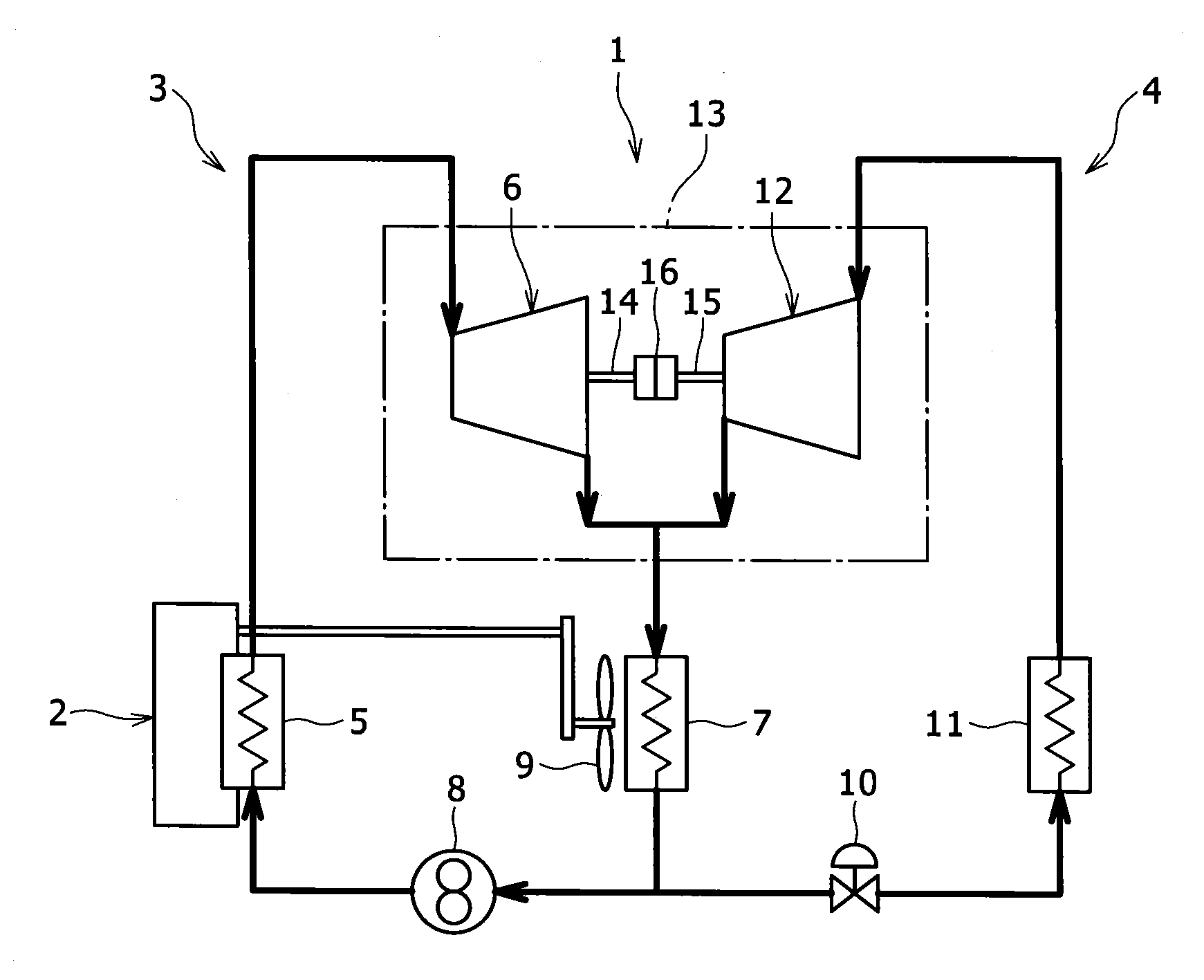
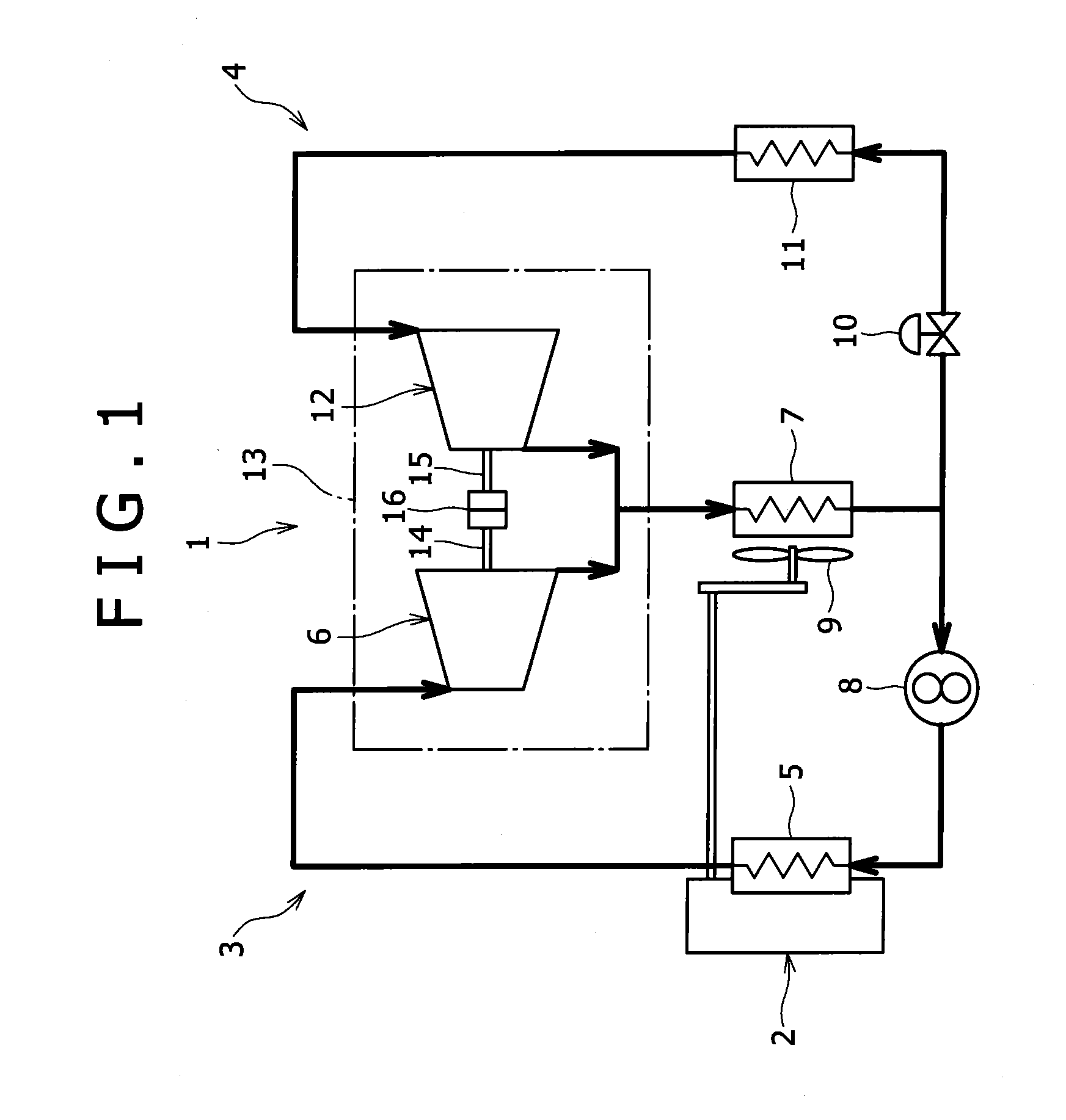
[0024]Preferred embodiments of the present invention will be then described in reference to the drawings. FIG. 1 shows a refrigerator 1 according to the present invention. The refrigerator 1 is intended to cool an automobile's cabin by recovering and converting thermal energy from an engine 2 of the automobile to power by a Rankine heat engine 3, and driving a refrigeration cycle heat engine 4 by this power.

[0025]The Rankine cycle heat engine 3 and the refrigeration cycle heat engine 4 constitute a partially-shared closed system with a heat medium (for example, R245fa) being sealed therein. The Rankine cycle heat engine 3 includes: a high-temperature evaporator 5 integrally formed with a cylinder block of an engine, and vaporizing the heat medium to cool the cylinder block with the vaporization heat of the heat medium; a screw expander 6 supplied with the heat medium evaporated in the high-temperature evaporator 5 and converting the expansion force of the heat medium to rotational f...

second embodiment

[0035]FIG. 4 shows a refrigerator 1a according to the present invention. In the following embodiments, the same reference number is assigned to the same component as described above to omit duplicate description. In the refrigerator la of this embodiment, a generator 27 is disposed within a casing 13 (intermediate space 21). A rotating shaft 28 of the generator 27 is connected respectively to the rotating shaft 14 of the screw expander 6 and the rotating shaft 15 of the screw compressor 12 by couplings 16.

[0036]The power generated by the generator 27 is drawn out of the casing 13 by a cable not shown, and stored in a battery of an automobile. Of course, this power can be directly consumed by other electric devices without through the battery.

[0037]This embodiment is applied when the rotating power which can be generated in the screw expander 6 of the Rankine cycle heat engine 3 is larger than the rotational power consumed by the screw compressor 12 of the refrigeration cycle heat en...

third embodiment

[0038]Further, FIG. 5 shows a refrigerator 1b according to the present invention. In this refrigerator 1b, the coupling which connects the rotating shaft 28 of the generator 27 to the rotating shaft 15 of the screw compressor 12 is composed of an electromagnetic clutch 29.

[0039]In this embodiment, the rotating shaft 15 of the screw compressor 12 is separated from the rotating shaft 14 of the screw expander 6 by throwing out the electromagnetic clutch 29, exhaust heat of the engine 2 is recovered by the Rankine cycle heat engine 3 with the refrigeration cycle heat engine 4 being halted, whereby the generator 27 can be driven to generate power. Thus, in this embodiment, when the cooling load is low as during winter season, the exhaust heat of the engine 2 can be recovered and effectively used.

[0040]In the present invention, the coupling 16 may be composed of another transmission mechanism such as a gear mechanism or chain-sprocket. Further, the generator 27 can be connected in paralle...


PUM


Abstract

A refrigerator of the present invention includes a Rankine cycle heat engine and a refrigeration cycle heat engine which share a condenser, and drives a compressor of the refrigeration cycle by an expander of the Rankine cycle. A screw expander and a screw compressor are set up within a common casing, and the exhaust side of a rotating shaft of the screw expander is connected to the discharge side of a rotating shaft of the screw compressor. Preferably, an intermediate space in which an exhaust passage of the screw expander and a discharge passage of the screw compressor are merged together and connected to a condenser, and a coupling which connects the rotating shaft of the screw expander to the rotating shaft of the screw compressor is housed is formed within the casing.

Description

BACKGROUND OF THE INVENTION[0001]1. Field of the Invention[0002]The present invention relates to a refrigerator.[0003]2. Description of the Related Art[0004]A cooling device for vehicle is disclosed in Japanese Patent Application Laid Open No. 56-43018, the cooling device being configured to drive a compressor included in a refrigeration cycle heat engine by a thermal expander.[0005]In this cooling device, a Rankine cycle is constituted so that a heat medium is vaporized by the heat of an engine to drive an expander, and the heat medium expanded by the expander is, after condensed by a radiator, returned to the engine by a pump, and the compressor of the refrigeration cycle is driven by the expander of the Rankine cycle.[0006]In this cooling device, the refrigeration cycle and the Rankine cycle use the same heat medium (refrigerant), and the refrigerant discharged by the compressor of the refrigeration cycle is condensed by the same radiator as in the Rankine cycle, and then supplie...

Claims


Application Information

Patent Timeline
Patent Type & Authority Applications(United States)
IPC IPC(8): F25D11/00F25B1/00
CPCF01D15/005F25B27/00F25B1/047F01K25/08F25B11/02
Inventor TSUBOI, NOBORU
Owner KOBELCO COMPRESSORS CORP
Why Eureka
Try Eureka