Oscillator circuit and method for gain and phase noise control

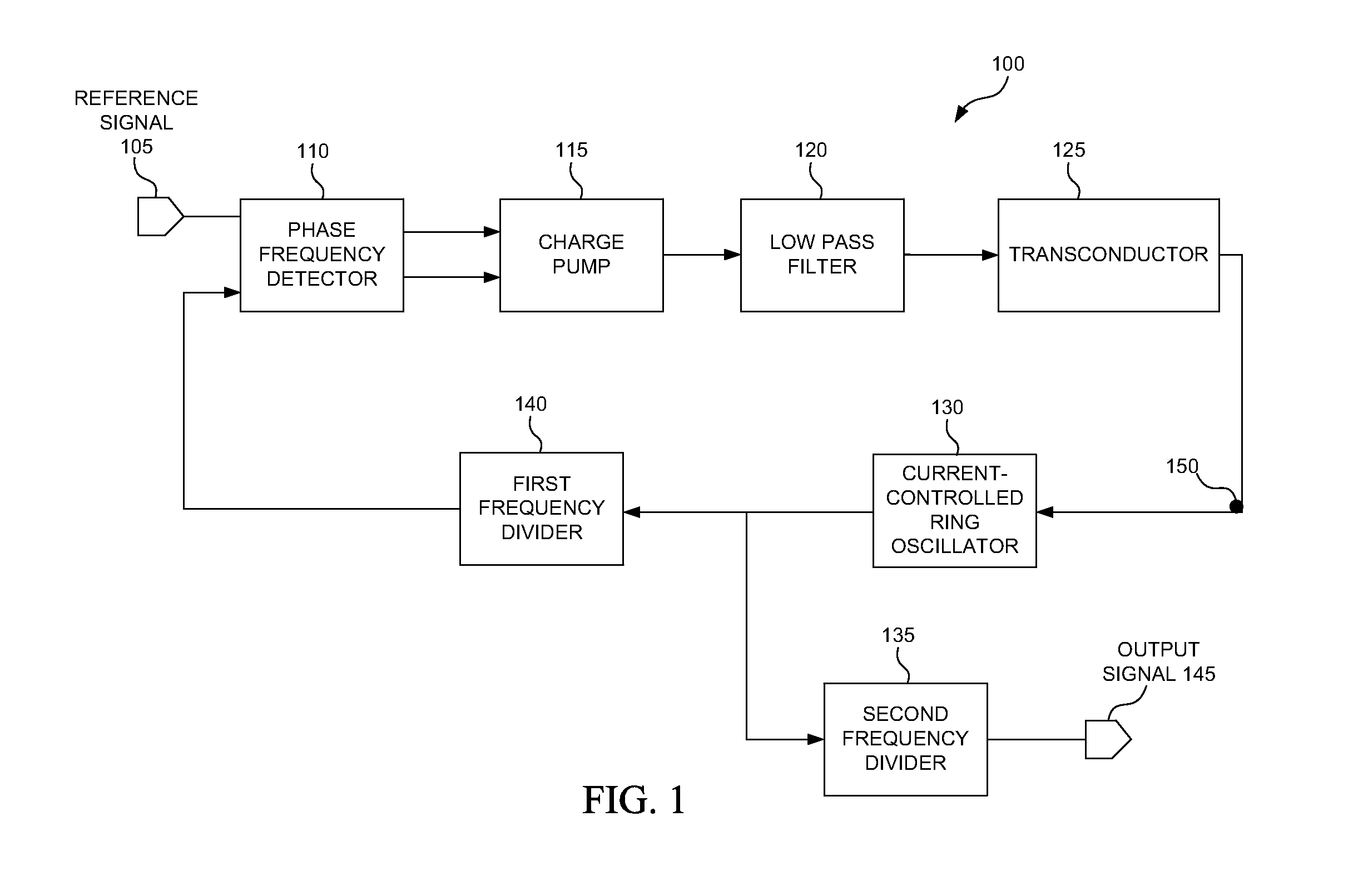
a phase noise and oscillator technology, applied in the field of electronic devices, can solve the problems of random jitter variation, requirement to limit the variance allowed in the bandwidth of device circuitry, and the feedback loop of the current-controlled ring oscillator b>130/b> may not be able to compensate for the gain and phase noise variations

Active Publication Date: 2012-04-19
TEXAS INSTR INC
View PDF4 Cites 10 Cited by
  • Summary
  • Abstract
  • Description
  • Claims
  • Application Information

AI Technical Summary

Benefits of technology

[0007]An oscillator circuit and method for gain and phase noise control are disclosed. In one aspect, a gain and phase noise controlled oscillator circuit includes a variable electronic oscillator for generating a clock signal, where frequency of the clock signal is controlled at least by a sense voltage received by the variable electronic oscillator or by one or more capacitive loads coupled to the variable electronic oscillator. The gain and phase noise controlled oscillator circuit also includes a tuning loop circuit coupled to the variable electronic oscillator, where the tuning loop circuit compares the sense voltage to a control voltage received by the tuning loop circuit and produces one or more correction signals based on the comparison, with the one or more capacitive loads c

Problems solved by technology

For many of these standards, requirements can limit the variance allowed with respect to bandwidth of device circuitry.
In addition, these communications standards require limits on random jitter variation, as large jitter variations require d

Method used


Image

  • Oscillator circuit and method for gain and phase noise control
  • Oscillator circuit and method for gain and phase noise control
  • Oscillator circuit and method for gain and phase noise control

Examples


Embodiment Construction

[0015]An oscillator circuit and method for gain and phase noise control are disclosed. The following description is merely exemplary in nature and is not intended to limit the present disclosure, applications, or uses. It should be understood that throughout the drawings, corresponding reference numerals indicate like or corresponding parts and features.

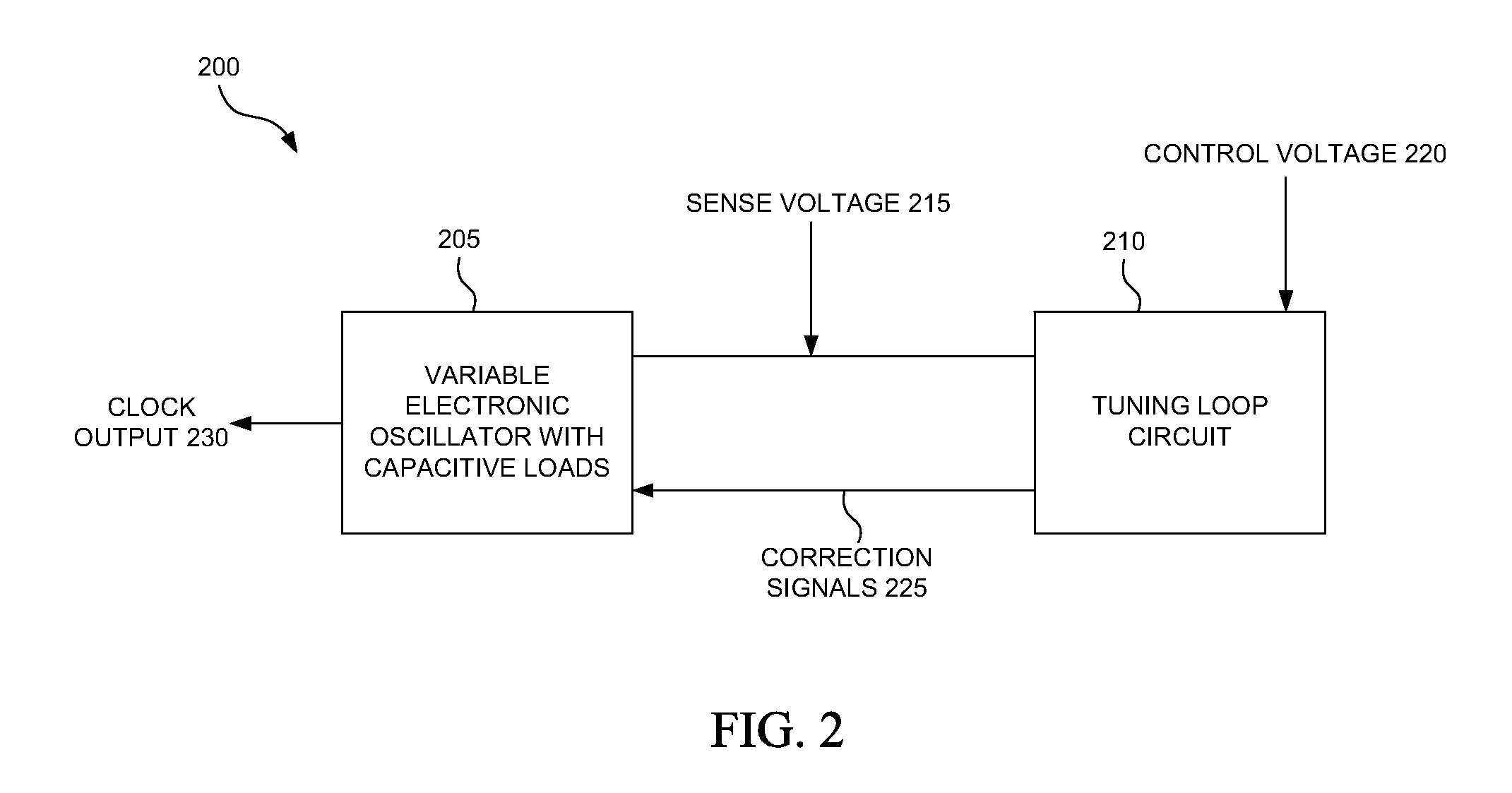
[0016]FIG. 2 illustrates a block diagram of an exemplary gain and phase noise controlled oscillator circuit 200, according to one embodiment. The gain and phase noise controlled oscillator circuit 200 includes a variable electronic oscillator 205 with capacitive loads and a tuning loop circuit 210. The variable electronic oscillator 205 generates clock signals at clock output 230, with a sense voltage 215 provided by the variable electronic oscillator 205. It is appreciated that the variable electronic oscillator 205 can be a number of oscillator circuits, including, but not limited to, voltage-controlled oscillators, current-control...


PUM


Abstract

An oscillator circuit and method for gain and phase noise control. A gain and phase noise controlled oscillator circuit includes a variable electronic oscillator and a tuning loop circuit. In operation, the variable electronic oscillator generates a clock signal and has a clock signal frequency that is controlled by a sense voltage received by the variable electronic oscillator or by one or more capacitive loads coupled to the variable electronic oscillator. Further, the tuning loop circuit is coupled to the variable electronic oscillator and compares the sense voltage to a control voltage received by the tuning loop circuit and produces one or more correction signals based on the comparison, where the one or more capacitive loads change capacitance based on the one or more correction signals.

Description

TECHNICAL FIELD[0001]Embodiments of the disclosure generally relate to the field of electronics, and more particularly to a gain and phase noise controlled oscillator circuit and method.BACKGROUND[0002]A number of communications standards are used in mainstream electronic devices, such as Universal Serial Bus (USB) 3.0, Frequency Modulation (FM), External Serial Advanced Technology Attachment (eSATA), and Peripheral Component Interconnect Express (PCIe). For many of these standards, requirements can limit the variance allowed with respect to bandwidth of device circuitry. For example, the PCIe standard limits the variation in loop bandwidth to 8 MHz to 16 MHz. In addition, these communications standards require limits on random jitter variation, as large jitter variations require designing circuits needing high power consumption.[0003]For a closed loop system, the open loop gain determines a number of characteristics for that system, including loop bandwidth, and the open loop gain ...

Claims


Application Information

Patent Timeline
IPC IPC(8): H03L7/08
CPCH03L2207/06H03L7/0995
Inventor KUMAR, AJAYPU, XIAONAGARAJ, KRISHNASWAMY
Owner TEXAS INSTR INC
Why Eureka
Try Eureka