
Water wave energy converter

Inactive Publication Date: 2012-04-26
AQUAGEN TECH
View PDF6 Cites 7 Cited by
  • Summary
  • Abstract
  • Description
  • Claims
  • Application Information

AI Technical Summary

Benefits of technology

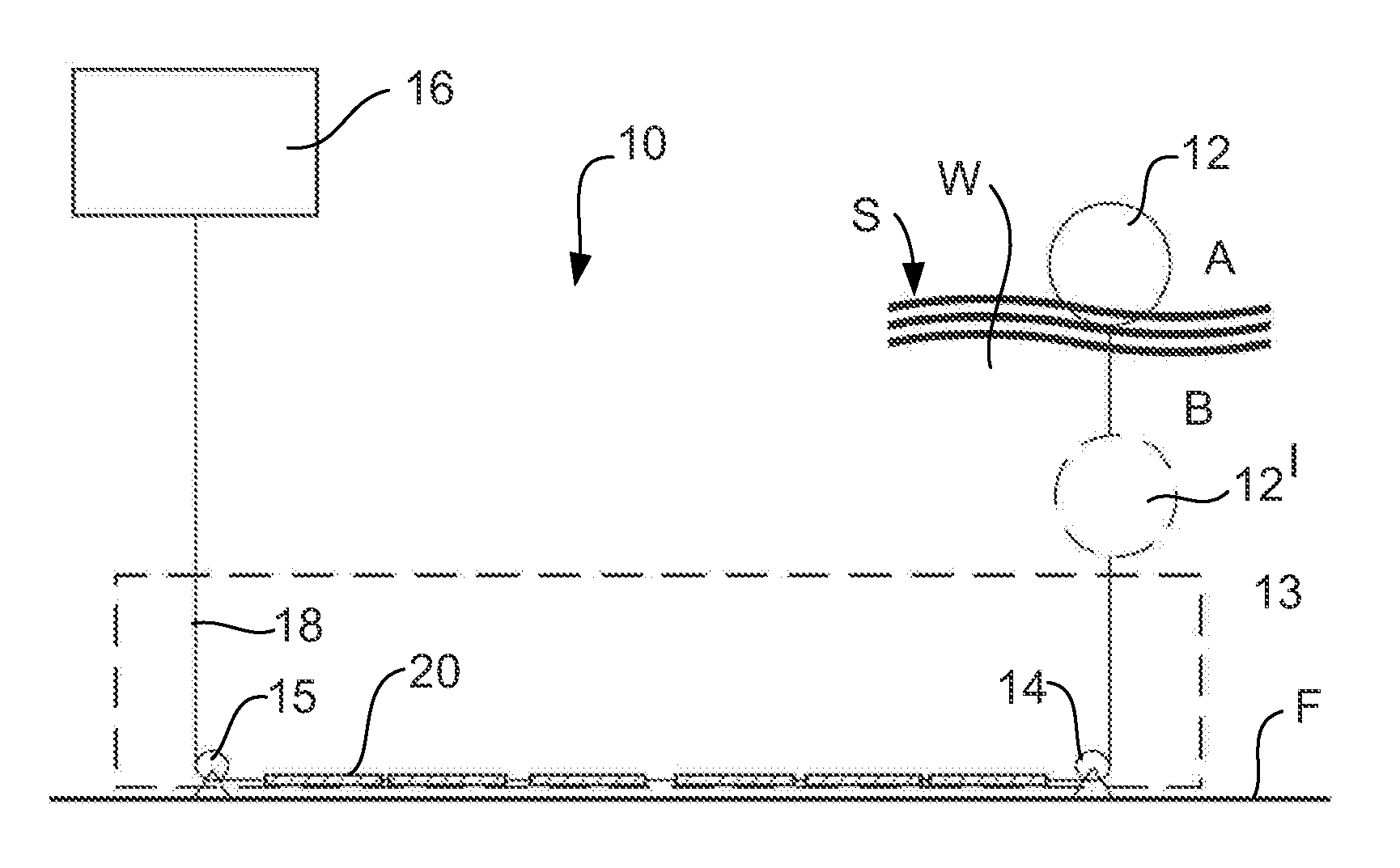
[0013]The water wave energy conversion system of the present invention employs a buoyant body which is situated in a body of water and an energy converter which is geographically separate to the buoyant body. The buoyant body is connected to the energy converter by an elongate connector via a one or a number of redirection devices. The separate location of the energy converter can allow for this component to be located out of the body of water, in a robust enclosure that is weather proofed. This separation can also allow the in-water components of the system to have a simple and robust construction enabling ease of maintenance and repair.
[0014]The effective length of the elongate connector can be varied / customised to suit particular water levels, tidal or weather events. The effective length of the elongate connector can be varied in some embodiments, to vary the depth of the buoyant body in the body of water relative to the water surface. Additionally, this enables the buoyant body to be lowered or raised relative to the surface of the body of water to tea the water wave based energy conversion system from damage during storm events.
[0015]The buoyant body and energy converter are operatively connected at their separate locations by an elongate connector. The elongate connector can be a cable, rope, chain, tether, cord, wire, or other flexible line, which is preferably resistant to corrosion or other deterioration from submergence in either fresh water or salt water, and having sufficient strength to withstand tension applied during operation of the system. In some embodiments, the elongate connector may include sections of higher strength material interlinked by a flexible connection section. The higher strength material may comprise larger diameter material, solid material, tubular material or the like. In some forms, the higher strength material comprises solid metal sections. The elongate connector is preferably constructed from a material that enables the elongate connector to undergo minimal changes in longitudinal length with changes in applied tensile force. In a preferred form, the elongate connector comprises a cable. The elongate connector may be fitted with at least one buoyancy element for reducing the net weight of the connector in water. The use of buoyancy elements reduces sagging of the elongate connector along its length so as to generally maintain a constant tension therein between the buoyant body and energy converter.

Problems solved by technology

However, it has been found that existing water wave-based energy conversion systems locate complex equipment in or under water.
This increases the capital and maintenance cost of the energy converter and thus increases the cost of energy conversion.
This arrangement also makes these energy converters susceptible to catastrophic failure during storm events due to the destructive forces the equipment is exposed to during such storm events.

Method used


Image

  • Water wave energy converter
  • Water wave energy converter
  • Water wave energy converter

Examples


Embodiment Construction

[0037]The present invention relates to a water wave-based energy conversion system for generating useful work from the natural motion of water waves, such as ocean waves. It should be understood that the system may be used in any body of water and that the ocean, shore and offshore and onshore structures illustrated in the drawings are shown for exemplary purposes only.

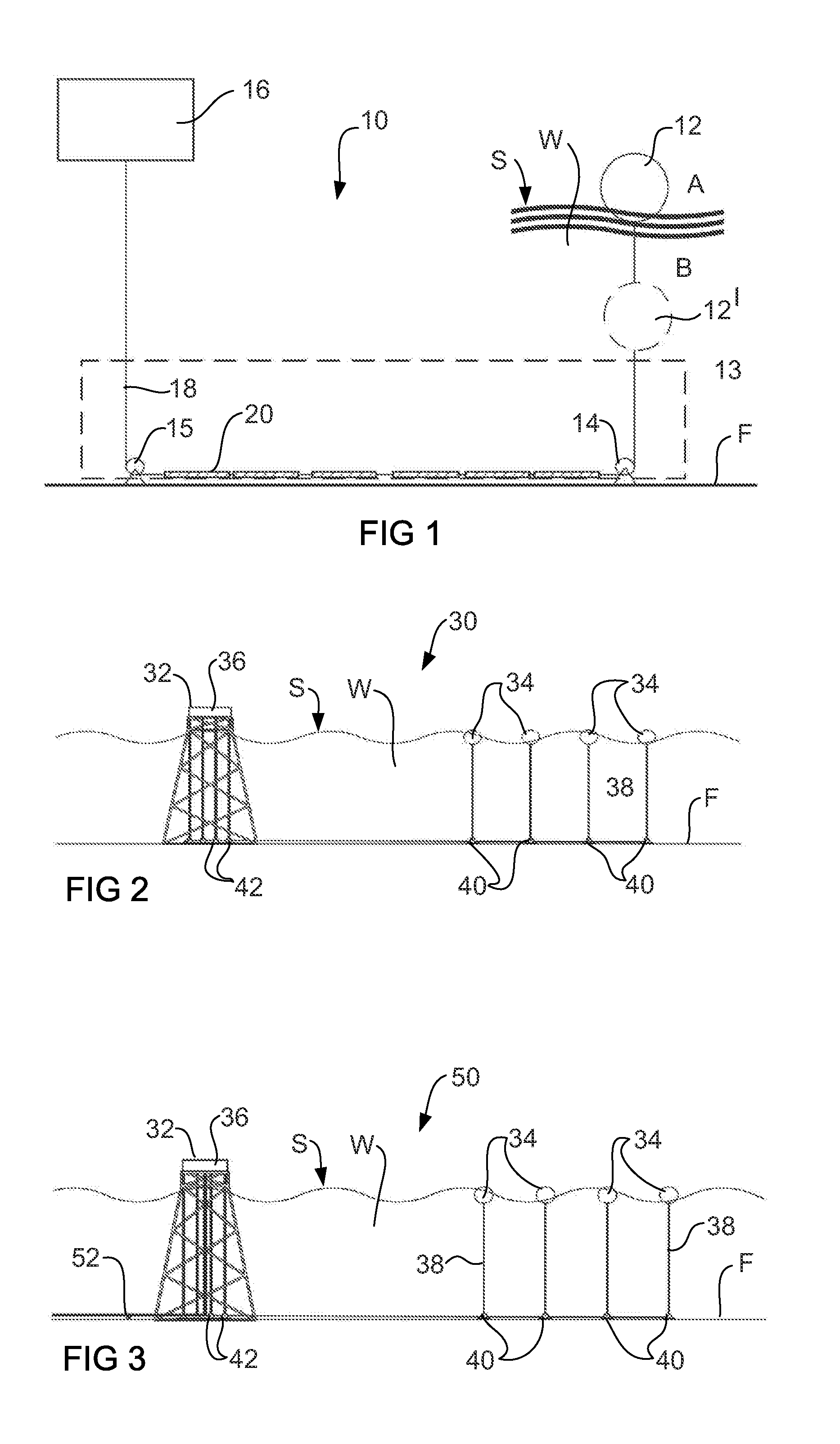
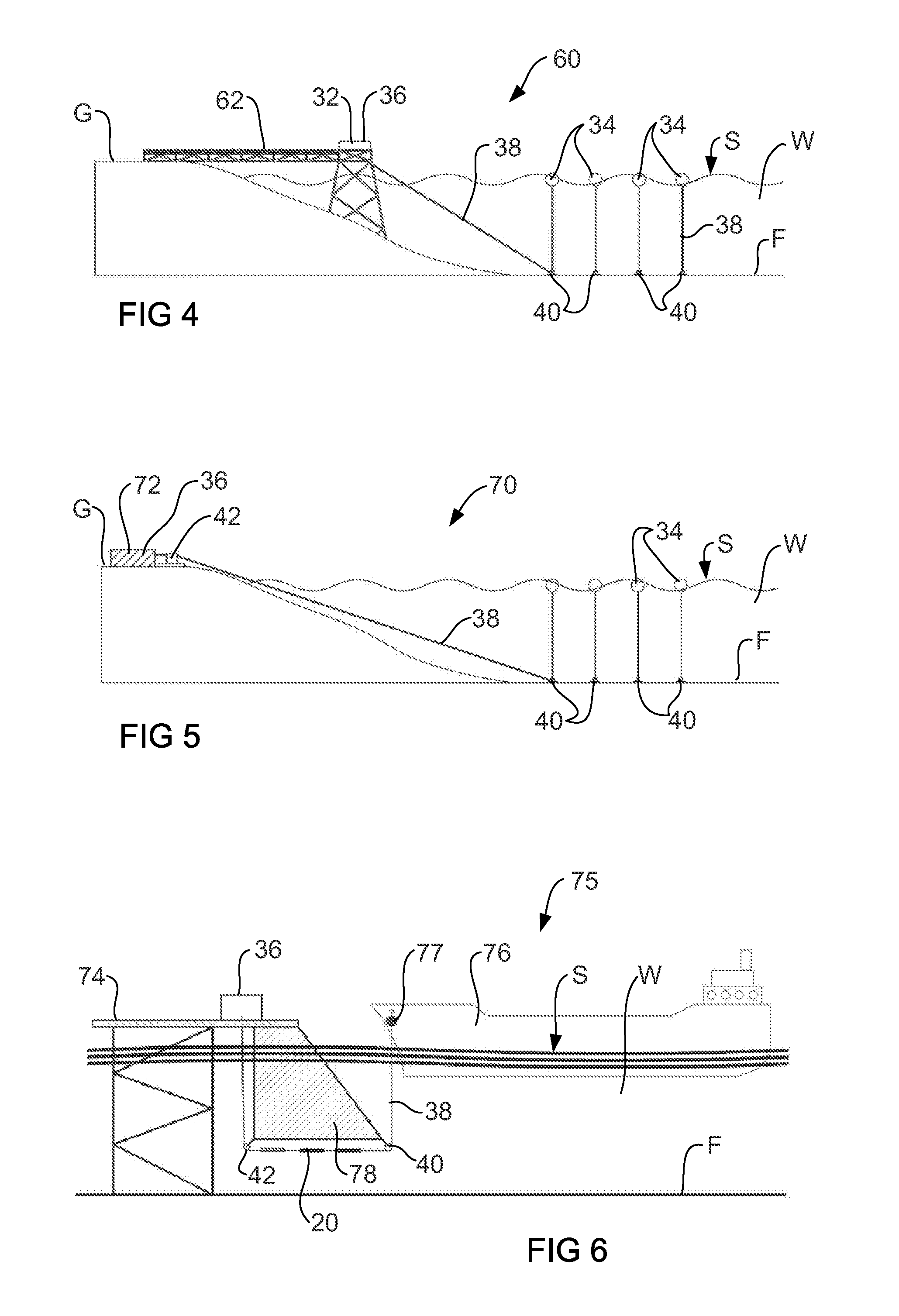
[0038]FIG. 1 provides a general schematic of a preferred form of the wave-based energy conversion system of present invention which illustrates the general concept provided by the system. The illustrated system 10 includes at least one buoyant body 12 floating either on or below the water surface S of a body of water W, an underwater redirection device 13, comprising pulleys 14 and 15 which are anchored on an underwater support surface, such as the ocean floor F, an energy converter 16 located at a separate location to the buoyant body 12, and an elongate connector, in this case cables 18 which operatively connect the...


PUM


Abstract

A water wave-based energy conversion system comprising: at least one buoyant body capable of floating on or below the surface of a body of water; at least one redirection device located at a stationary position; an energy converter; and at least one elongate connector operatively coupling the at least one buoyant body to the energy converter through the at least one redirection device. In use, the elongate connector transfers motion of the at least one buoyant body resulting from waves in the body of water to the energy converter for conversion into useful energy forms or products.

Description

FIELD OF THE INVENTION[0001]The present invention relates to a water wave-based energy conversion system that converts the energy of water waves into useful energy forms or products.BACKGROUND OF THE INVENTION[0002]The following discussion of the background to the invention is intended to facilitate an understanding of the invention. However, it should be appreciated that the discussion is not an acknowledgement or admission that any of the material referred to was published, known or part of the common general knowledge as at the priority dale of the application.[0003]Water wave-based energy conversion systems extract useful energy from the wave motion of a body of water. Existing arrangements typically include a buoyant body which floats on or just below the surface of the body of water, and an onboard energy converter. The energy converter includes a mechanical component that is moved from the wave directly actuating a water immersed component such as a paddle, blade or wheel, or...

Claims


Application Information

Patent Timeline
IPC IPC(8): F03B13/16
CPCE02B9/08Y02E10/38F03B13/1885Y02E10/30
Inventor BOYD, NICHOLASBUDEN, MARTIN GEORGE
Owner AQUAGEN TECH
Learn More