Light emitting diode projector

a projector and light-emitting diode technology, applied in lighting and heating apparatus, instruments, condensers, etc., can solve the problems of heating equipment, inability to meet the requirements of lighting equipment, inability to meet the requirements of lighting equipment, etc., to achieve uniform illumination plane intensity, reduce toxic materials, and efficient coupling

Active Publication Date: 2012-04-26
BRUKILACCHIO THOMAS J
View PDF0 Cites 30 Cited by
  • Summary
  • Abstract
  • Description
  • Claims
  • Application Information

AI Technical Summary

Benefits of technology

[0012]The invention herein describes a light emitting diode (LED) light source comprising an LED die or a closely packed die array or matrix of die arrays substantially and efficiently coupled to non-imaging collection optics which act to homogenize the LED output providing at the non-imaging collection optics exit aperture a high degree of near field intensity uniformity and a reduced far field extent substantially preserving the étendue (area, solid angle, index squared product) at the LED output. The near field, at the output of the collection optics, in turn, is imaged by a relay lens to an illumination plane a specific distance away. This projector provides a solid state light source of much improved stability, lifetime, illumination plane intensity uniformity, reduction of toxic materials, and specific spectral content required by today's most demanding industrial, medical, biological, and commercial illumination source applications relative to mercury, xenon, metal halide, and tungsten based lamp systems.
[0013]The primary components of the LED projector system include a high thermal conductivity LED COB board, direct attached LED die and wire bonds, a high collection efficiency non-imaging optic to collect and homogenize the LED emission, and an adjustable focus imaging lens system to relay the LED output to the illumination plane. The output aperture of the collection optic can include various apertures or spectral filters to modify the output of the light at the illumination plane. Alternatively, a zoom lens system could be used to change the magnification to achieve an adjustable illumination pattern size at a specific image distance. This LED based projector technology opens up new applications that were not previously either technically feasible, cost feasible or both.

Problems solved by technology

This LED based projector technology opens up new applications that were not previously either technically feasible, cost feasible or both.

Method used


Image

  • Light emitting diode projector
  • Light emitting diode projector
  • Light emitting diode projector

Examples


Embodiment Construction

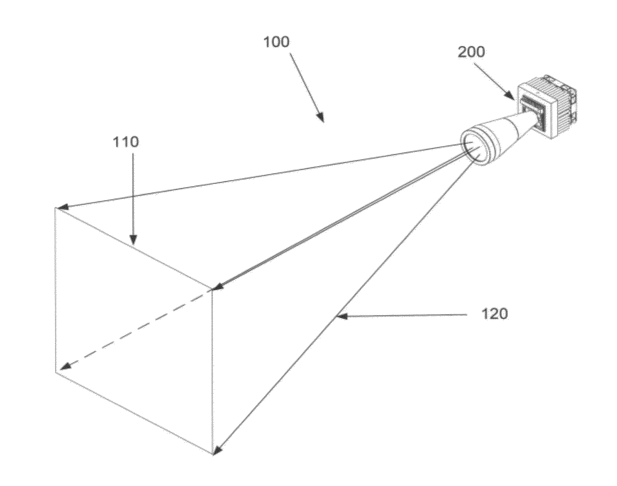
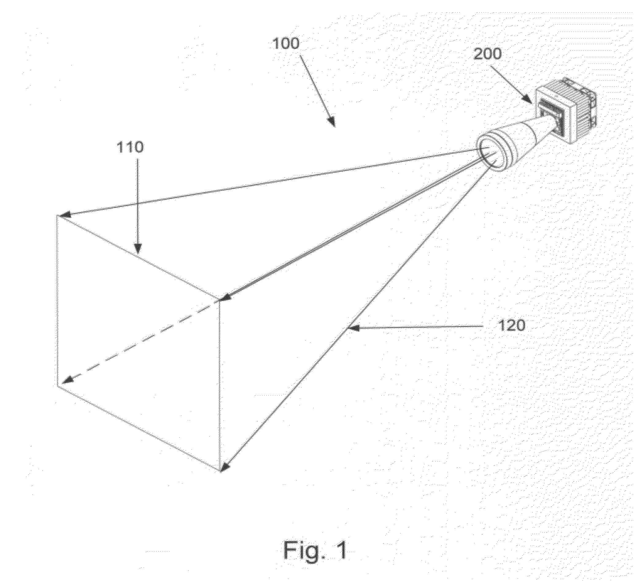
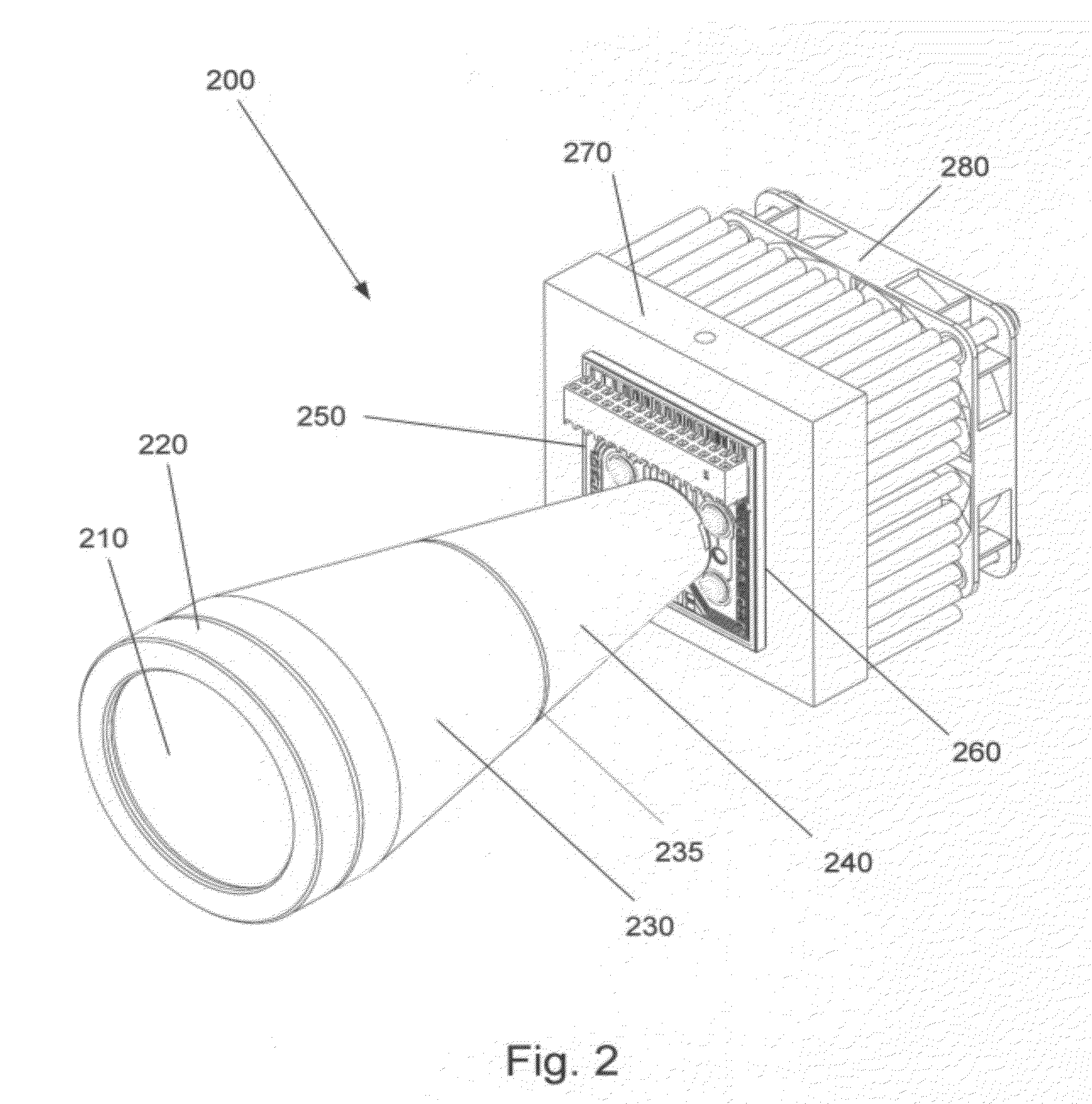
[0036]The present invention relates to Light Emitting Diode (LED) projection systems. The emission from an LED die or die array attached to a high thermal conductivity substrate is collected by a non-imaging optic and subsequently re-imaged by a system of lenses to the illumination plane some distance from the output aperture of the lens system. The LED board is in turn thermally coupled to a heat sink typically cooled by a fan or other air or water supply. The projector can illuminate a well defined area with the high uniformity and control over the spectrum and intensity pattern required of high performance industrial, medical, and biological illumination and image detection systems. Recently the advent of high brightness LEDs has enabled such projection systems to replace short arc mercury, xenon, and metal halide lamps as well as tungsten halogen. This has led to significant improvements in light stability, spectral control, lifetime, and energy efficiency afforded by the use of...


PUM


Abstract

The invention relates to a light emitting diode (LED) light source comprising an LED die, or a closely packed die array or matrix of die arrays, substantially and efficiently coupled to non-imaging collection optics. The non-imaging collection optics operate to provide a homogenized LED output having a near field whose intensity is highly uniform and a reduced far field extent substantially preserving the étendue (area, solid angle, index squared product) of the LED output. The near field, in turn, is imaged by a downstream relay lens to an illumination plane a specific distance away.

Description

CROSS REFERENCE TO RELATED APPLICATION[0001]This application claims the benefit of priority from U.S. Provisional Patent Application No. 61 / 406,962 entitled LIGHT EMITTING DIODE PROJECTOR which was filed on Oct. 26, 2010 in the name of Thomas J. Brukilacchio, the entire contents of which are incorporated herein by reference.FIELD OF THE INVENTION[0002]This invention generally relates to the uniform projection of the emission from light emitting diodes (LEDs) onto a plane a finite distance from the emitting aperture for use in applications requiring high intensity uniform illumination over the spectral range including ultraviolet (UV) to mid infrared (MIR). Applications include industrial illumination such as machine vision, medical such as tissue illumination or fluorescence, biological such as illumination to aid in the growth of algae in well plates or as a multi-spectral illumination source for fluorescence excitation and subsequent detection by a camera imaging system.BACKGROUND...

Claims


Application Information

Patent Timeline
Patent Type & Authority Applications(United States)
IPC IPC(8): F21V1/00
CPCG01N21/8806G02B27/0955G02B19/0028G02B19/0066G02B27/0983
Inventor BRUKILACCHIO, THOMAS J.
Owner BRUKILACCHIO THOMAS J
Why Eureka
Try Eureka