Apparatus of manufacturing silicon carbide single crystal

Inactive Publication Date: 2012-05-03
BRIDGESTONE CORP
View PDF2 Cites 5 Cited by
  • Summary
  • Abstract
  • Description
  • Claims
  • Application Information

AI Technical Summary

Benefits of technology

[0005]Therefore, the present invention has been made to solve the above problems, an object of the present invention is to provide an apparatus of manufacturing a silicon carbide single crystal in which the structure of a heating member is simple and temperature control is easy.
[0008]As described above, a coil pitch is adjusted by changing the number of windings of the single heating coil, so that a tight winding portion and a loose winding portion are formed in one heating coil, resulting in the achievement of a simple structure and the improvement of power efficiency.
[0012]According to the present invention, it is possible to achieve an apparatus of manufacturing a silicon carbide single crystal in which a structure is simple, power efficiency is high, and temperature control is easy.

Problems solved by technology

Thus, the structure of the heating member may be complicated, and it may be difficult to perform temperature control for adjusting a heating temperature by adjusting the amount of the current flowing through the upper coil and the lower coil.

Method used


Image

  • Apparatus of manufacturing silicon carbide single crystal
  • Apparatus of manufacturing silicon carbide single crystal
  • Apparatus of manufacturing silicon carbide single crystal

Examples


example 1

Conventional Example 1

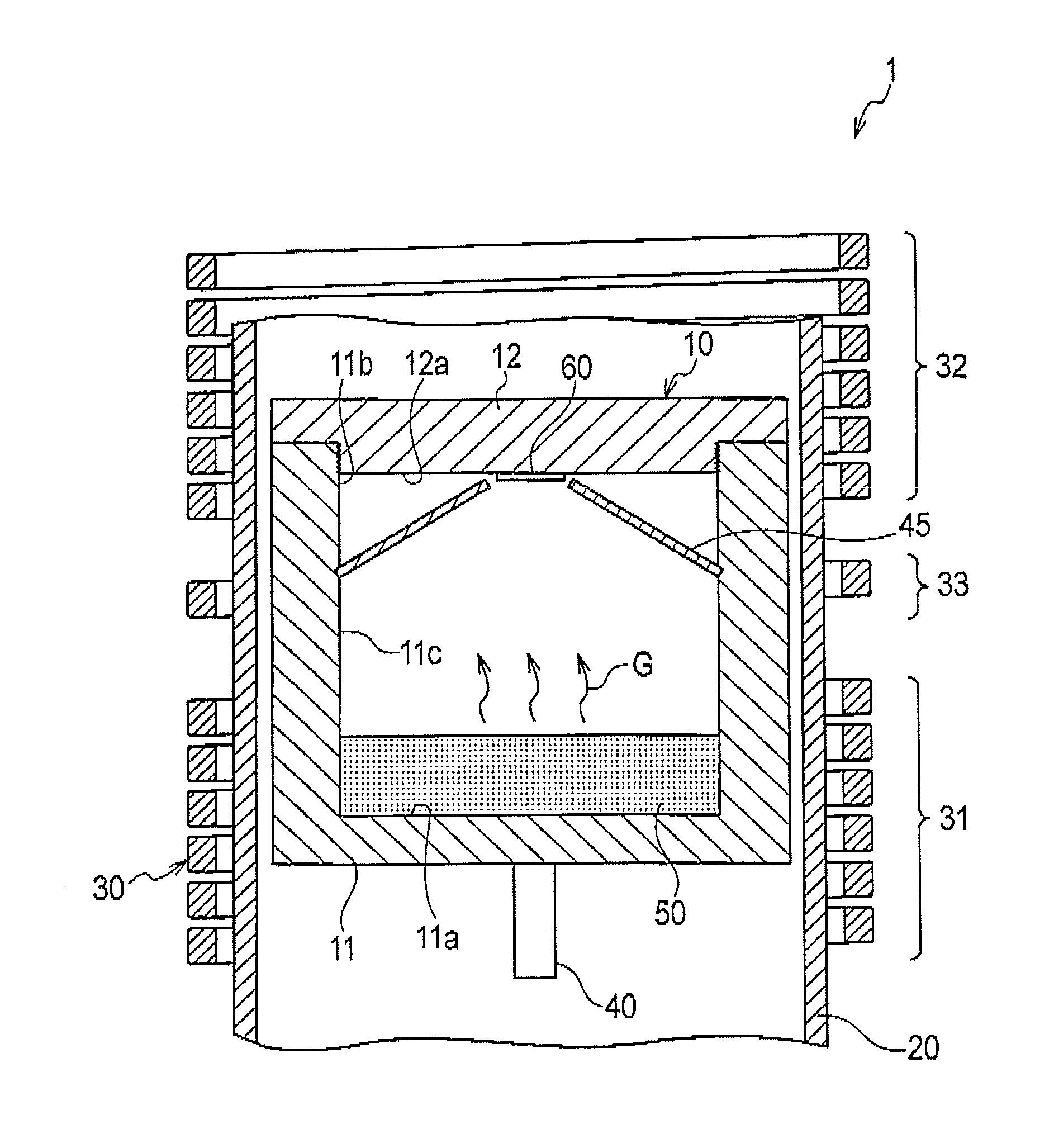
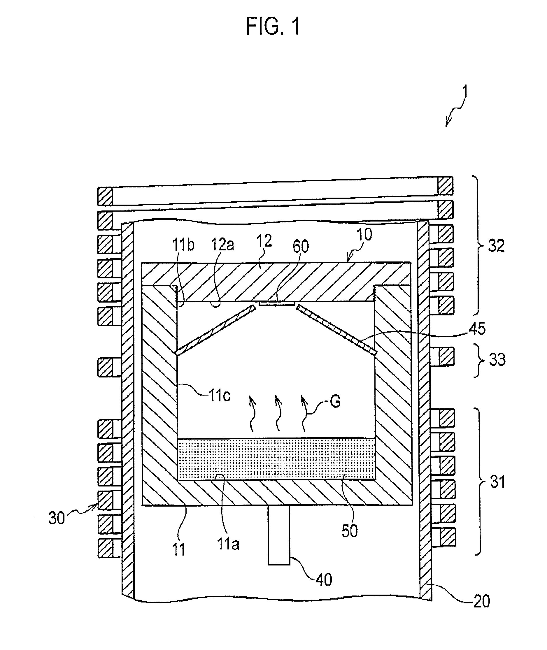
[0064]FIG. 4 illustrates the sections of the graphite crucible 10 and the heating coil 70 according to conventional example 1. The graphite crucible 10 had approximately the same structure as FIG. 1. That is, the sublimation material 50 was accommodated in the bottom unit of the crucible main body 11, the seed crystal 60 was attached to the inner surface 12a of the crucible, and the guide member 45 was provided around the seed crystal. Further, the heating coil 70 wound in a spiral shape around the outer periphery of the graphite crucible 10, which was spaced apart from the graphite crucible 10, was placed. The number of windings of the heating coil 70 was 10 and the heating coil 70 was wound at the same pitch. The center in the height direction of the heating coil 70 was made to correspond to the height of the upper surface of the sublimation material 50. In such a state, a current was allowed to flow through the heating coil 70 to heat the outer periphery of ...

example 2

Conventional Example 2

[0066]In the conventional example 2, an apparatus as approximately same as the conventional example 1 of FIG. 4 was used. However, the height position of a heating coil 80 was lowered than the conventional example 1, and the center in the height direction of the heating coil 80 was arranged corresponding to the height position of the bottom unit 11a of the crucible main body 11.

[0067]As a consequence, as illustrated in FIG. 9, the temperature difference ΔT between the surface of the sublimation material and the surface of the seed crystal was 60° C. Thus, the condition 1 was not satisfied.

Example of Present Invention

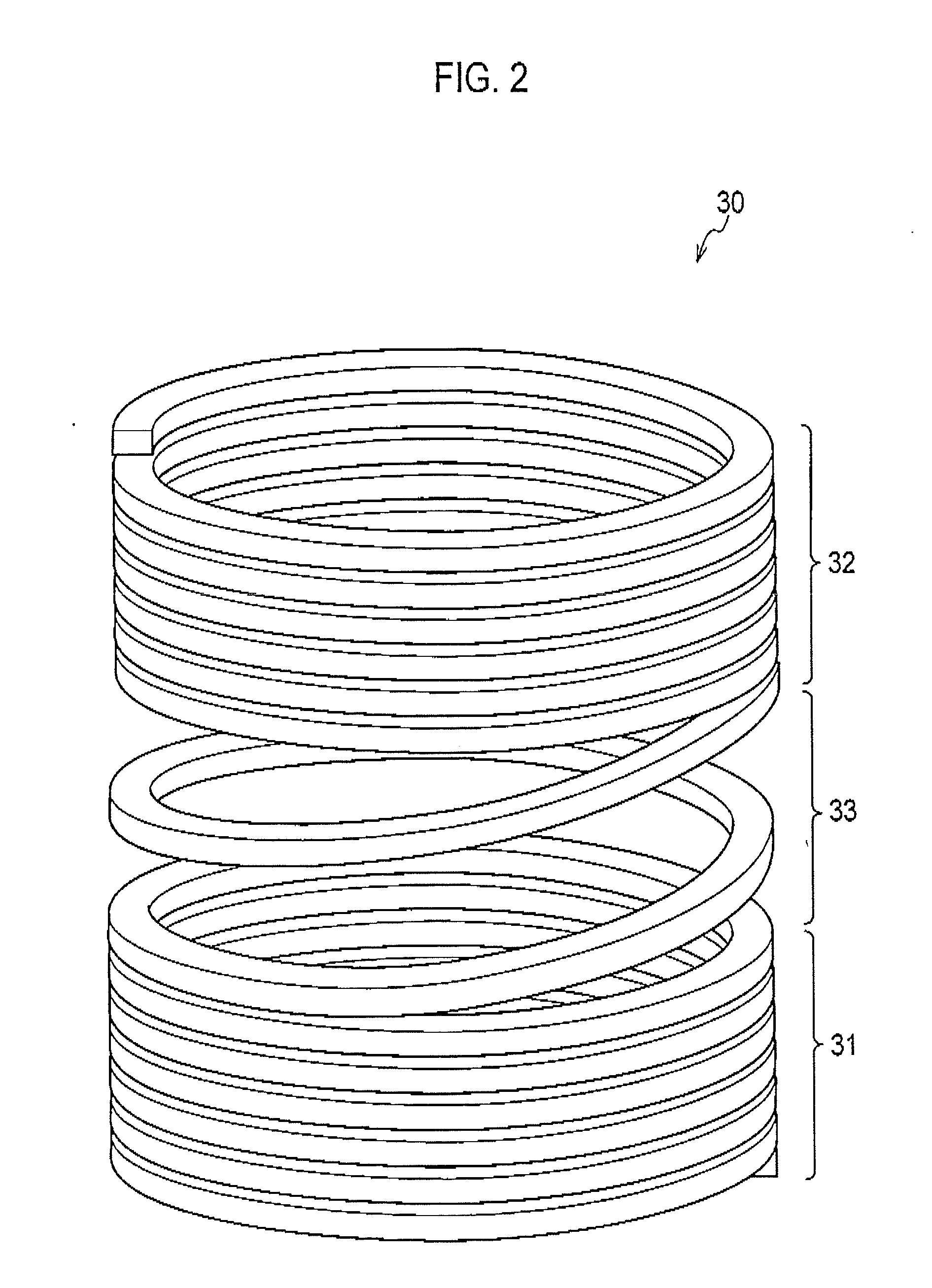
[0068]In the example of the present invention, a heating coil 90 included an upper coil 91 arranged at the upper side and a lower coil 92 arranged at the lower side, and the upper coil 91 and the lower coil 92 were integrally connected to each other using one single coil.

[0069]As a consequence, as illustrated in FIG. 10, the temperature difference Δ...


PUM

PropertyMeasurementUnit
Heightaaaaaaaaaa

Abstract

A apparatus (1) for manufacturing a silicon carbide single crystal comprises a graphite crucible (10) and configured so that the upper opening (11b) of a cylindrical crucible main body (11) has been blocked with a cover member (12), and a heating member comprising a single heating coil continuously wound around the outer periphery of the graphite crucible (10) and in which a sublimation material (50) is held on the bottom (11a) and a seed crystal (60) is attached to the inner surface (12a) of the crucible. The lower coil (31), which has wound around the bottom (11a) of the crucible main body (11), and the upper coil (32), which has wound around the cover member (12), have coil pitches (P1 and P3) which are smaller than the coil pitch (P2) of the central coil (33), which has wound around a center in the height-direction of the crucible main body (11).

Description

TECHNICAL FIELD[0001]The present invention relates to an apparatus of manufacturing a silicon carbide single crystal used when manufacturing a silicon carbide single crystal.BACKGROUND ART[0002]Conventionally, a sublimation recrystallization method has been disclosed as a silicon carbide single crystal manufacturing method for manufacturing a silicon carbide single crystal (hereinafter, referred to as a single crystal, where appropriate) from a seed crystal and a sublimation material, which include silicon carbide. A manufacturing apparatus used for the sublimation recrystallization method roughly includes a crucible and a heating member, and has a structure in which a powdery sublimation material is contained in a crucible main body, an upper opening of the crucible main body is blocked with a cover member, a seed crystal is attached to the inner surface of the crucible, and a heating coil (a heating member) is wound around the outer periphery of the crucible main body. Then, a cur...

Claims


Application Information

Patent Timeline
IPC IPC(8): C30B23/06
CPCC30B29/36C30B23/06
Inventor SEIKI, WATARUKONDO, DAISUKE
Owner BRIDGESTONE CORP
Why Eureka
Try Eureka