Plate heat exchanger

a heat exchanger and plate technology, applied in the direction of heat exchanger fastening, lighting and heating apparatus, ice removal, etc., can solve the problems of reducing the heat exchange efficiency of the heat exchanger, so as to achieve a considerably simpler and better heat exchange

Active Publication Date: 2012-05-03
SARTORIUS STEDIM BIOTECH GMBH
View PDF12 Cites 27 Cited by
  • Summary
  • Abstract
  • Description
  • Claims
  • Application Information

AI Technical Summary

Benefits of technology

[0014]It is thereby possible, in particular, to configure the first plates and the second plates such that they are structurally identical, wherein the second plates are mounted such that they are turned correspondingly through 180° in relation to the first plates. As a result, only one mold is required for the first and second plates, which makes production considerably simpler.
[0015]According to a preferred embodiment of the invention, the flow channels of the plates respectively have flow guides. The flow guides are here configured as barriers or partitions disposed in the flow channels. The partitions of flow channels for the first fluid and of flow channels for the second fluid are preferably arranged perpendicular to each other. This contributes to a better heat exchange.

Problems solved by technology

A drawback in this case is that the plates are mutually sealed in a relatively complex manner by means of seals, or, insofar as they are formed from a ceramic material, it is known to join them integrally in a complex process to form a monolithic block.
Both apparatuses which are produced according to this process are correspondingly complex and expensive to make.
A drawback in this case is that the plates have no internal flow distributor or flow guide.
In the course of assembly, difficulties arise in ensuring a leak-tightness necessary for sterile applications.

Method used


Image

  • Plate heat exchanger
  • Plate heat exchanger
  • Plate heat exchanger

Examples


Embodiment Construction

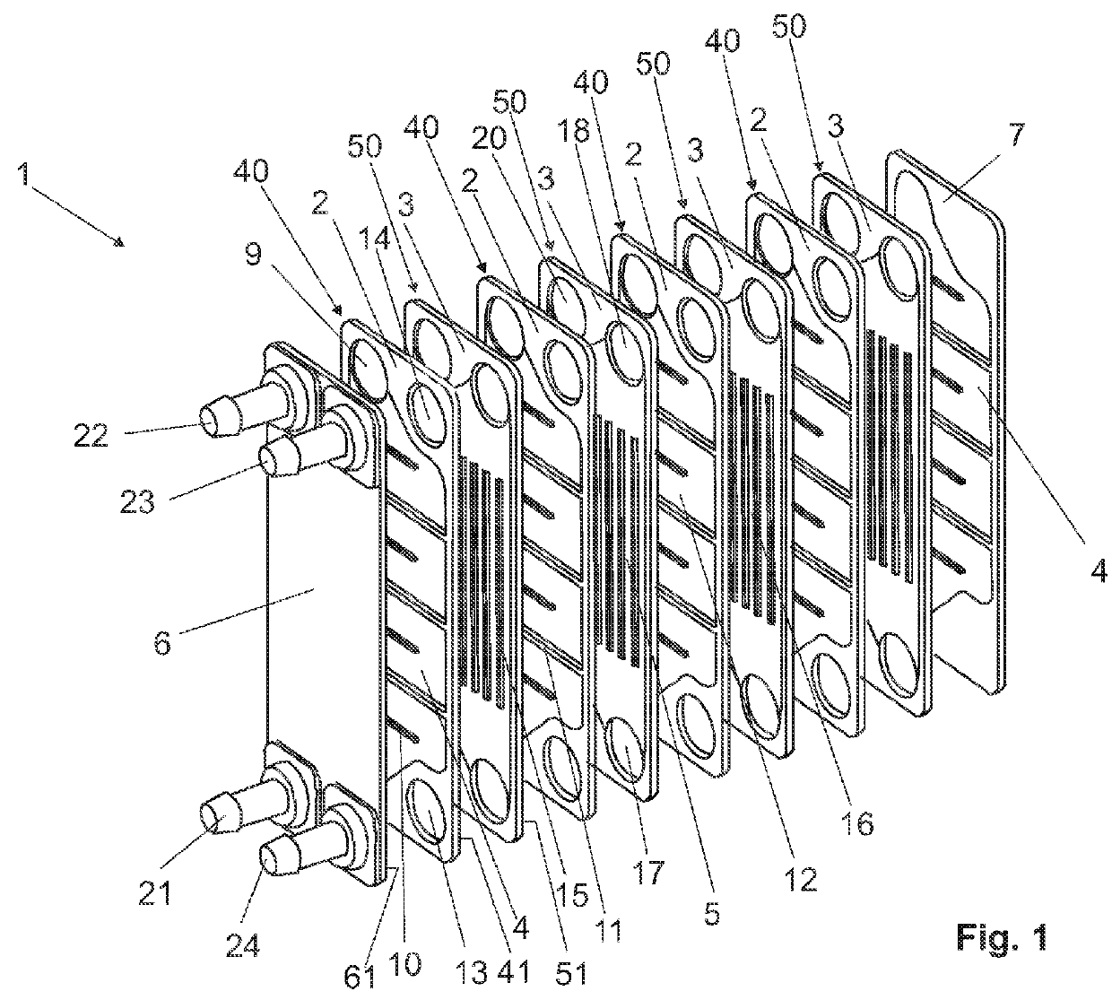
[0033]A plate heat exchanger 1 substantially consists of a plurality of first plates 40 and second plates 50 having flow channels 4, 5, a front plate 6 and an end plate 7.

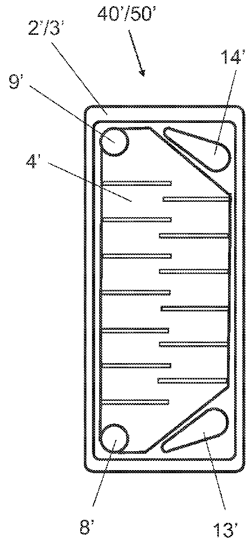
[0034]The first plate 40 has a front side 2 and a rear side 41. In the vertical direction, the first plate 40 has in its corners at bottom left and top left through openings 8, 9 for a first fluid. On the front side 2 of the plate 40 is disposed a planar depression, which forms the flow channel 4 and extends into the through openings 8, 9. In the horizontal direction away from the side walls, the flow channel 4 has flow barriers 10, 11 of a flow guide 12, which overlap in the horizontal direction and thus form a serpentine flow channel 4. The rear side 41 is configured flat, i.e. without a flow channel.

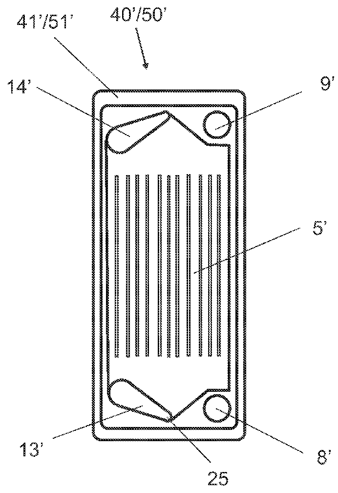
[0035]Outside the flow channel 4, the first plate 40 has through openings 13, 14 respectively at top right and bottom right in the vertical direction.

[0036]The second plate 50 has on its front side 3 a planar depress...


PUM

PropertyMeasurementUnit
temperatureaaaaaaaaaa
heat exchangeaaaaaaaaaa

Abstract

The invention relates to a plate heat exchanger comprising a plurality of plates having flow channels, wherein a first plate has a front side having at least one flow channel for a first fluid and a second plate has a front side having at least one flow channel for a second fluid, and wherein the plates have through openings via which the flow channels for the same fluid are respectively connected to one another, wherein a front plate, which is placed in front of the front side of the first plate, has ports for the first fluid and for the second fluid, wherein an end plate forms the end of the aligned plates, wherein the plates and ports are formed from plastic, and wherein the plates are bonded or welded tightly together.

Description

BACKGROUND OF THE INVENTION[0001]1. Field of the Invention[0002]The invention relates to a plate heat exchanger comprising a plurality of plates having flow channels, wherein a first plate has a front side having at least one flow channel for a first fluid and a second plate has a front side having at least one flow channel for a second fluid, and wherein the plates have through openings via which the flow channels for the same fluid are respectively connected to one another.[0003]2. Description of the Related Art[0004]In pharmacy, biotechnology and in the food industry, gaseous or perhaps liquid mediums frequently have to be heated or cooled. In order to perform such thermal processes, heat exchangers are normally used. Heat is here transported from the warmer medium to the colder medium. The mediums are mutually separated. In this context, there is a need for heat exchangers which are very cheap in terms of material and production.[0005]DE 10 2006 013 503 A1 discloses a plate heat...

Claims


Application Information

Patent Timeline
Patent Type & Authority Applications(United States)
IPC IPC(8): F28F3/08
CPCF28D9/005F28F17/005F28F2280/06F28F2275/02F28F2275/06F28F21/06
Inventor REIF, OSCAR-WERNERVAN DEN BOOGAARD, JUERGENWEISSHAAR, STEFAN
Owner SARTORIUS STEDIM BIOTECH GMBH
Why Eureka
Try Eureka