Solid oxide fuel cell

a fuel cell and solid oxide technology, applied in the field of solid oxide fuel cells, can solve the problems of gas leakage, defect likely to occur, etc., and achieve the effect of reducing gas leakag

Inactive Publication Date: 2012-05-03
NGK INSULATORS LTD
View PDF7 Cites 12 Cited by
  • Summary
  • Abstract
  • Description
  • Claims
  • Application Information

AI Technical Summary

Benefits of technology

[0010]In the solid oxide fuel cell above, the sealing portion that does not contain either Ni or ZrO2

Problems solved by technology

However, the present inventors have found that there are still some problems as follows with the conventional technique.
As a result, a crack in t

Method used


Image

  • Solid oxide fuel cell
  • Solid oxide fuel cell
  • Solid oxide fuel cell

Examples


example 1

1. EXAMPLE 1

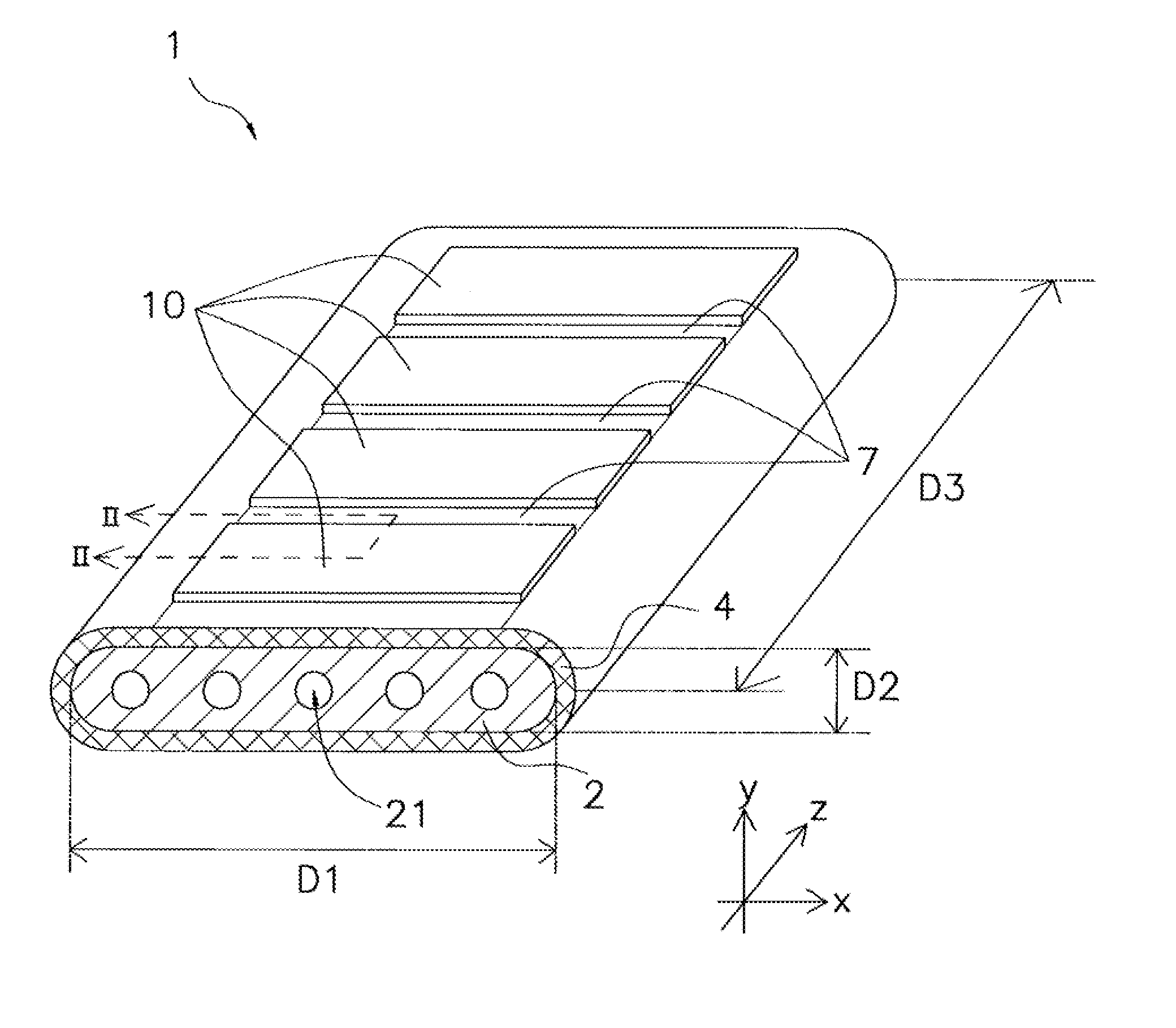
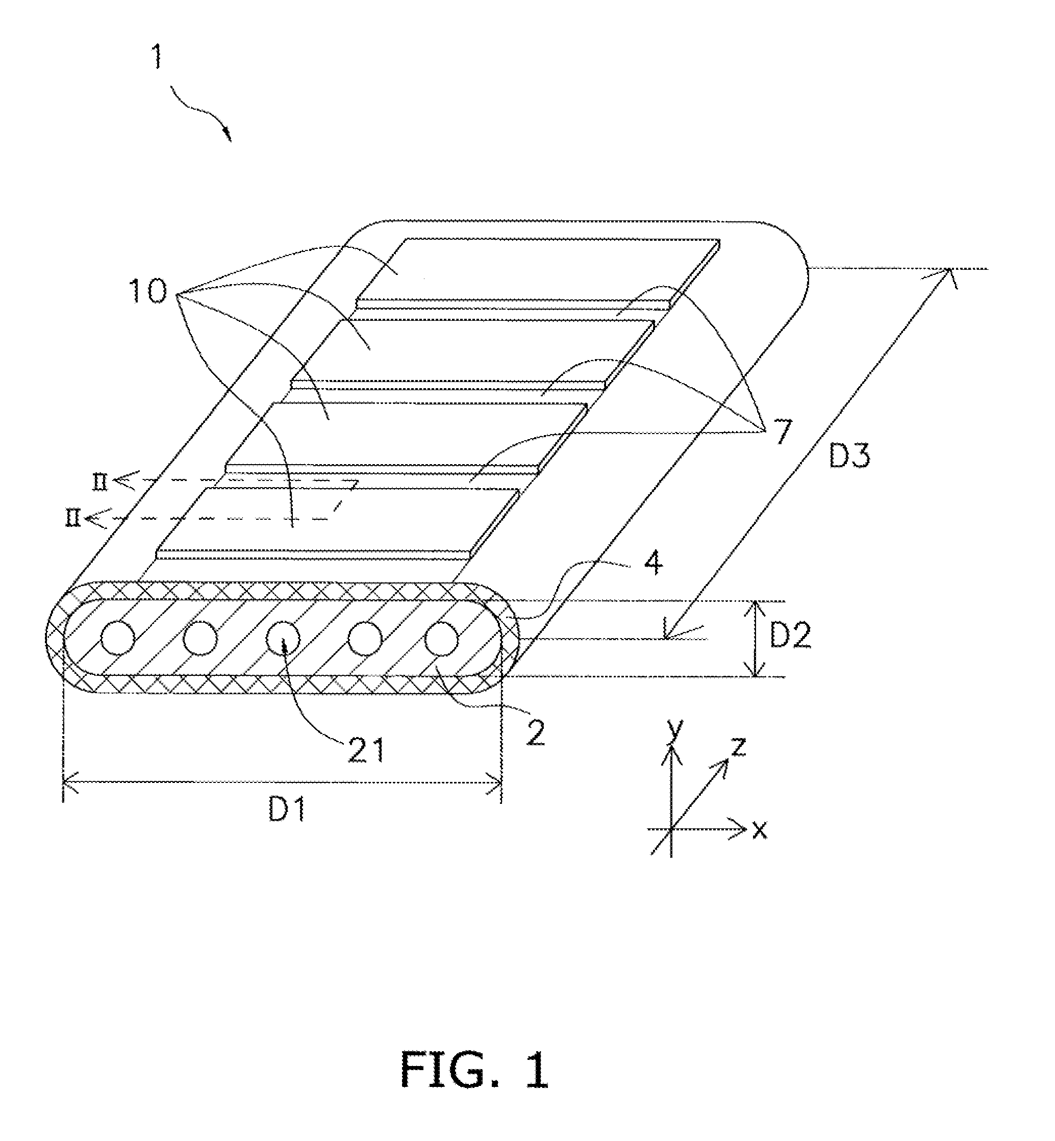
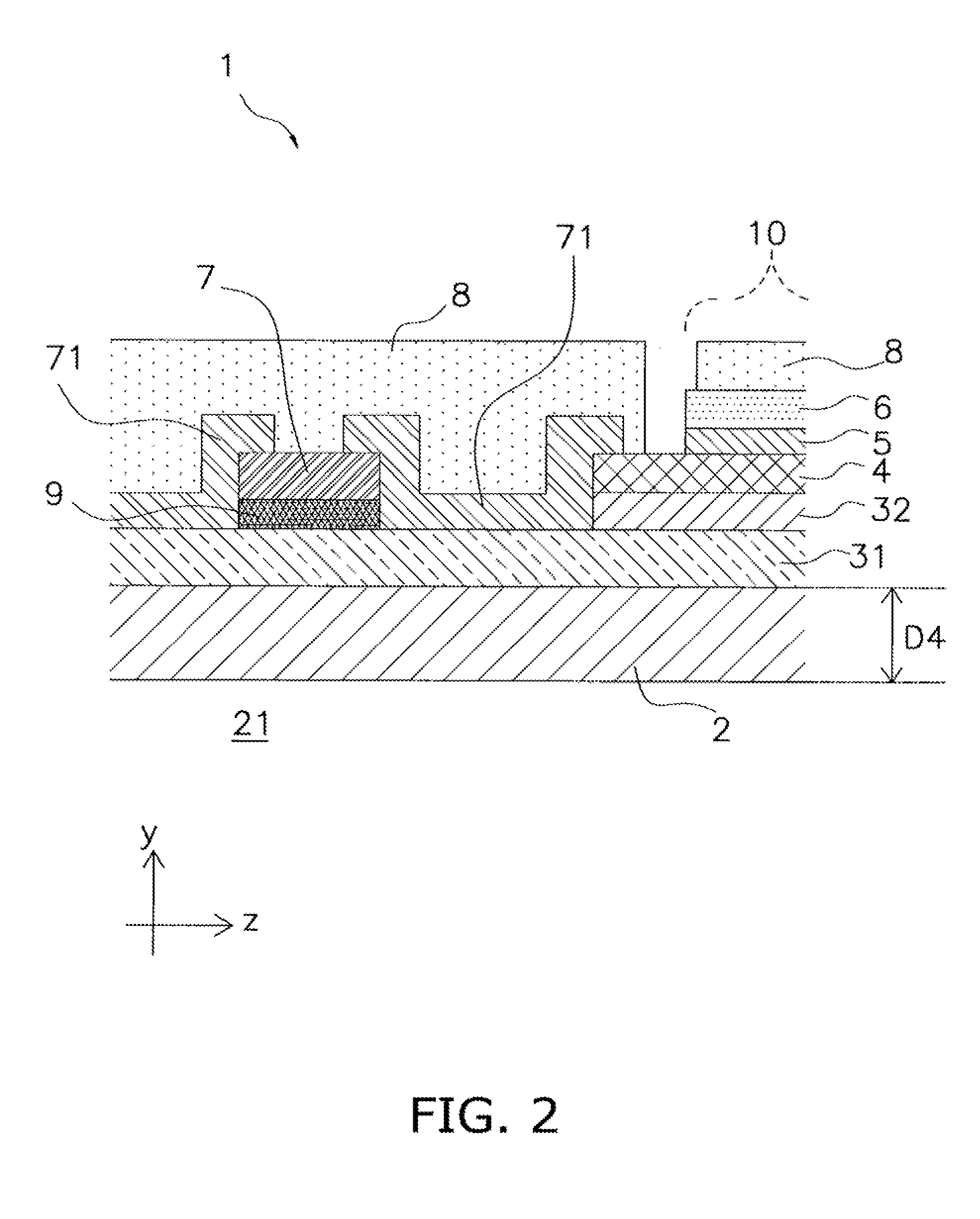
[0030]As shown in FIGS. 1 and 2, the segmented-in-series solid oxide fuel cell (hereinafter simply referred to as a “fuel cell”) 1 of this example includes a support substrate 2, an anode (including an anode current collecting layer 31 and an anode active layer 32), an electrolyte layer (solid electrolyte layer) 4, a barrier layer 5, a cathode 6, an interconnector 7, a sealing portion 71, and a current collector 8. In FIG. 1, the current collector 8 is not shown for convenience of description.

[0031]The fuel cell 1 has power generating elements 10. The power generating element 10 includes the anode (31, 32) and the cathode 6 that corresponds to the anode (31, 32). Specifically, the power generating element 10 includes the anode (31, 32), the electrolyte layer 4, the barrier layer 5, and the cathode 6 that are stacked in the thickness direction (y-axis direction) of the support substrate 2.

[0032]The support substrate 2 has a shape that is flat and elongated in one directio...

examples

[0112]Preparation of Samples

[0113]Evaluation samples illustrated in FIG. 17 were prepared as described below.

[0114]A porous substrate 30 as shown in FIG. 17 (corresponding to the above-described anode current collecting layer 31 and support substrate 2) was formed as follows. NiO powder and Y2O3 powder were mixed so that Ni / Y2O3 ratio is 40:60 vol % after reduction process. Cellulose powder in an amount of 20 wt % relative to the total weight of NiO powder and Y2O3 powder was added as a pore forming agent, and mixed. The mixture was granulated by an SD method (spray dry method). The resulting granules were subjected to uniaxial pressing at a pressure of 40 MPa, thus giving a green body in a pellet form (thickness of 2000 μm). The diameter of the pellets was 50 mm.

[0115]An interlayer 9 (thickness of 5 μm, diameter of 25 mm) was formed as follows. NiO powder and (La, Ca)CrO3 powder (Ca content of 20 mol % in A site) were mixed in a ratio of Ni:(La, Ca)CrO3=1:1 (volume ratio) after red...


PUM

PropertyMeasurementUnit
Weight ratioaaaaaaaaaa

Abstract

A solid oxide fuel cell includes two or more power generating elements each having a cathode, an anode, and an electrolyte layer placed between the cathode and the anode; an interconnector electrically connecting the power generating elements and containing a chromite-based material; and a sealing portion provided between the electrolyte layer and the interconnector and not containing either Ni or ZrO2.

Description

CROSS-REFERENCE TO RELATED APPLICATIONS[0001]This application claims priority to Japanese Patent Application No. 2010-245599 filed on Nov. 1, 2010, Japanese Patent Application No. 2011-156138 filed on Jul. 14, 2011 and U.S. Provisional Application No. 61 / 509,244 filed on Jul. 19, 2011. The entire disclosure of Japanese Patent Application Nos. 2010-245599 and 2011-156138 and U.S. Provisional Application No. 61 / 509,244 are hereby incorporated herein by reference.BACKGROUND OF THE INVENTION[0002]1. Field of the Invention[0003]The present invention relates to a solid oxide fuel cell.[0004]2. Description of the Related Art[0005]JP 2009-134930A discloses a segmented-in-series fuel cell. This fuel cell has an insulating substrate and a plurality of cells provided on the insulating substrate. The fuel cell has an anode (fuel electrode), an electrolyte layer made from yttria-stabilized zirconia (YSZ: (Y2O3)x(ZrO2)1-x (wherein x is 0.05 to 0.15)), and a cathode (air electrode) that are stacke...

Claims


Application Information

Patent Timeline
IPC IPC(8): H01M8/24
CPCH01M8/0219H01M8/1286H01M8/243H01M8/004H01M8/0282H01M8/0276H01M8/2425C04B35/053C04B35/488C04B2235/3206C04B2235/3208C04B2235/3248H01M8/0271H01M2008/1293Y02E60/50
Inventor YOSHIDA, TOSHIHIRORYU, TAKASHIOKAMOTO, TAKUNISHITOBA, MASARUOHMORI, MAKOTO
Owner NGK INSULATORS LTD
Why Eureka
Try Eureka