Process for producing solar cell module

Inactive Publication Date: 2012-05-03
ASAHI GLASS CO LTD
View PDF5 Cites 21 Cited by
  • Summary
  • Abstract
  • Description
  • Claims
  • Application Information

AI Technical Summary

Benefits of technology

[0035]According to the process for producing a solar cell module of the present invention, the thin-film type solar cell device can be made to be less susceptible to breakage, it is possible to increase the interface bonding strength between the re

Problems solved by technology

However, such a method is cumbersome and not economical.
However, the method (1) have the following problems.The EVA layer is exposed on the side surface of the produced solar cell module, whereby moisture or corrosive gas is likely to infiltrate from the interface between the EVA layer and the front surface material or the back surface material at the side surface.At the time of laminating the sealing material film of EVA and the back surface material (or the front surface material) on the surface of the glass substrate on the side where the thin-film type solar cell device is formed, it is likely that an excessive pressure or heat is exerted to the thin-film type solar cell device, whereby the thin-film type solar cell device is likely to be damaged.On the other hand, if the pressure or heat is suppressed to be low so that the thin-film type solar cell device will not be damaged, the interface bonding strength between the EVA layer and the thin-film type solar cell device, or the interface bonding strength between the EVA layer and the back surface material (or the front surface material) in the produced solar cell module tends to be inadequate, whereby peeling is likely to occur at the surface of the EVA layer, and further moisture or corrosive gas is more likely to infiltrate from the portion where the interface bonding strength is inadequate at the side surface of the solar cell module.
Further, it is also likely that void spaces such as bubbles will remain between the EVA layer and the back surface material (or the front surface material).
However, in the above laminate, the gap between the front surface material and the back surface material becomes narrow, whereby it becomes difficult to fill the liquid state curable resin composition, and spaces (bubbles) are likel

Method used


Image

  • Process for producing solar cell module
  • Process for producing solar cell module
  • Process for producing solar cell module

Examples


first embodiment

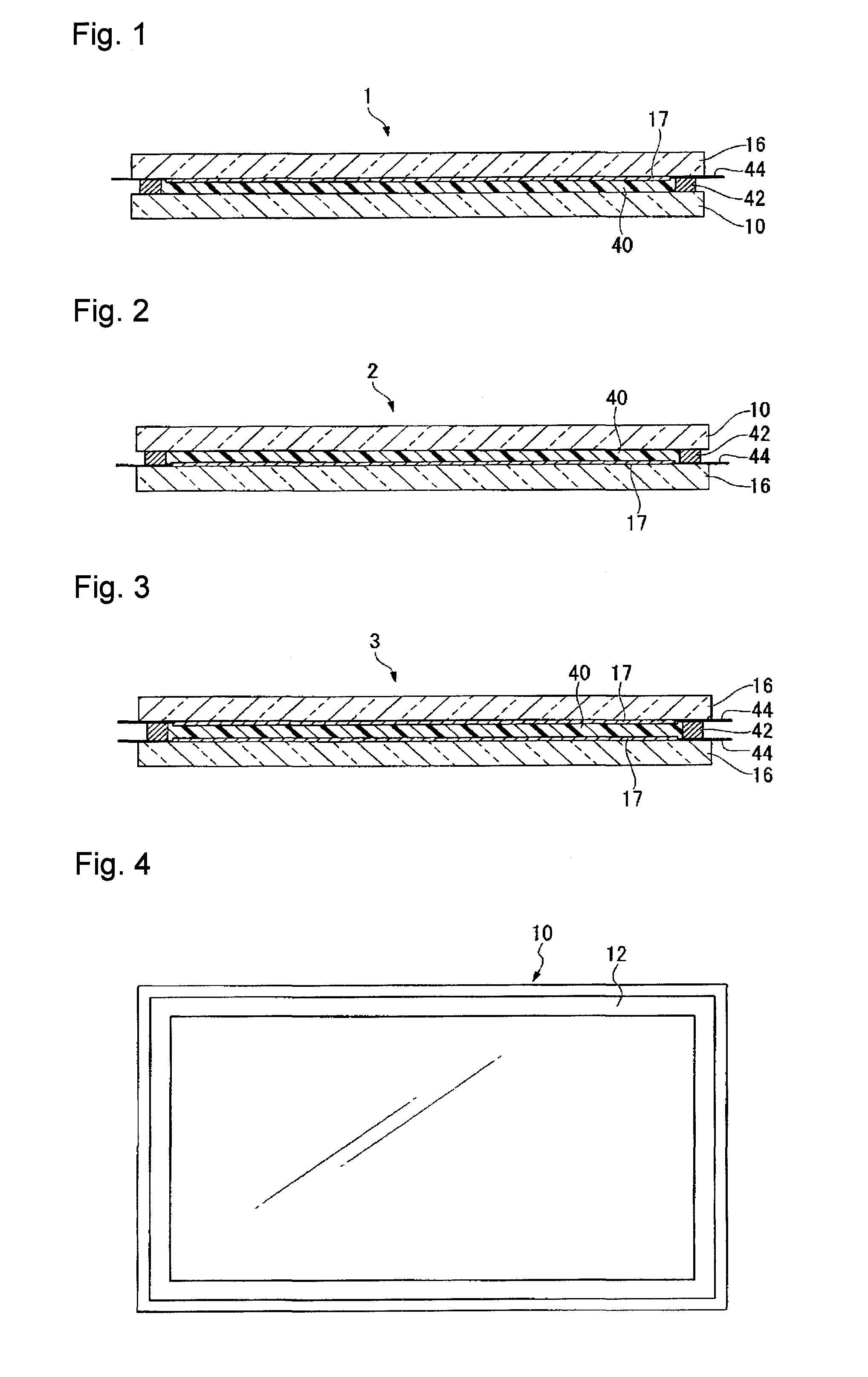
[0057]FIG. 1 is a cross-sectional view illustrating an example of the first embodiment of the solar cell module in the present invention.

[0058]The solar cell module 1 comprises a glass substrate 16 as the front surface material, a transparent surface material 10 as the back surface material, a resin layer 40 interposed between the glass substrate 16 and the transparent surface material 10, a thin-film type solar cell device 17 formed on the surface of the glass substrate 16 on the resin layer 40 side, a seal part 42 enclosing the periphery of the resin layer 40, and an electric wire 44 connected to the thin-film type solar cell device 17 and extending through the seal part 42 to the exterior. Here, in a case where the glass substrate 16 as the above front surface material becomes a second surface material, the transparent surface material 10 as the back surface material becomes a first surface material, and in a case where the glass substrate 16 as the above front surface material b...

second embodiment

[0087]FIG. 2 is a cross-sectional view illustrating an example of the second embodiment of the solar cell module in the present invention.

[0088]The solar cell module 2 comprises a transparent surface material 10 as the front surface material, a glass substrate 16 as the back surface material, a resin layer 40 interposed between the transparent surface material 10 and the glass substrate 16, a thin-film type solar cell device 17 formed on the surface, on the resin layer 40 side, of the glass substrate 16, a seal part 42 enclosing the periphery of the resin layer 40, and an electric wire 44 connected to the thin-film type solar cell device 17 and extending through the seal part 42 to the exterior. Here, in a case where the transparent surface material 10 as the above front surface material becomes a second surface material, the glass substrate 16 as the back surface material becomes a first surface material, and in a case where the transparent surface material 10 as the above surface ...

third embodiment

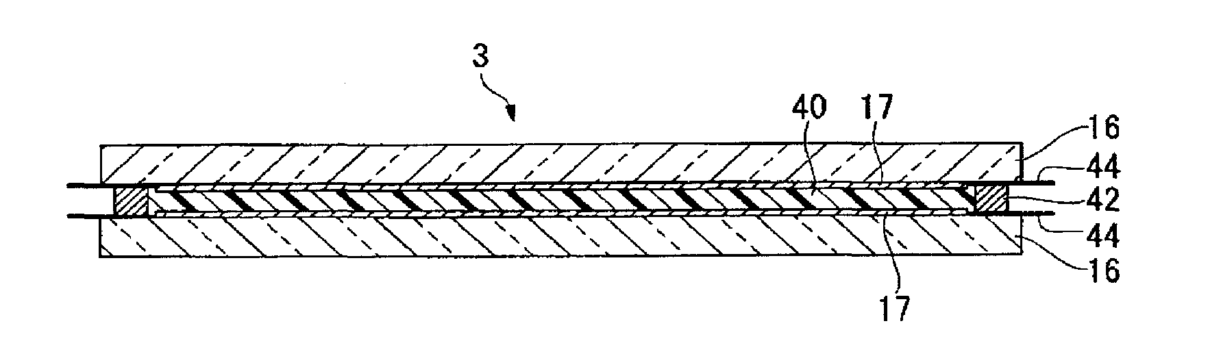
[0104]FIG. 3 is a cross-sectional view illustrating an example of the third embodiment of the solar cell module in the present invention.

[0105]The solar cell module 3 comprises a glass substrate 16 as the front surface material, a glass substrate 16 as the back surface material, a resin layer 40 interposed between the pair of glass substrates, a total of two layer thin-film type solar cell devices 17 formed on the surfaces, on the resin layer 40 side, of the respective glass substrates 16, a seal part 42 enclosing the periphery of the resin layer 40, and electric wires 44 connected to the thin-film type solar cell devices 17 and extend through the seal part 42 to the exterior. Here, in a case where the glass substrate 16 as the above front surface material becomes a second surface material, the glass substrate 16 as the back surface material becomes a first surface material, and in a case where the glass substrate 16 as the above front surface material becomes a first surface materi...


PUM


Abstract

A process for producing a solar cell module, including (a) forming a seal part made of e.g. a double sided adhesive tape on the edge of a surface of a transparent surface material (first surface material), (b) supplying a liquid state photocurable resin composition to the region enclosed by the seal part, (c) laminating, in a reduced pressure atmosphere of not more than 100 Pa, on the photocurable resin composition, a glass substrate (second surface material) having a thin-film type solar cell device formed, to obtain a laminated material having the photocurable resin composition hermetically sealed, and (d) curing the photocurable resin composition in such a state that the laminated material is placed in a pressure atmosphere of not less than 50 kPa to form a resin layer.

Description

TECHNICAL FIELD[0001]The present invention relates to a process for producing a solar cell module wherein a thin-film type solar cell device is protected by transparent surface materials.BACKGROUND ART[0002]A solar cell module has a solar cell device sealed between a transparent front surface material to constitute a light-receiving surface and a back surface material by a sealing material such as a resin.[0003]As the solar cell device, the following ones are known as generally classified.[0004]A crystal type solar cell device formed from a silicon wafer (also called solar cell).[0005]A thin-film type solar cell device formed by carrying out patterning sequentially every time when a transparent electrode layer, a photoelectric conversion layer and a backside electrode layer are, respectively, formed on the surface of a substrate.[0006]A thin-film type solar cell device formed by carrying out patterning sequentially every time when a backside electrode layer, a photoelectric conversi...

Claims


Application Information

Patent Timeline
IPC IPC(8): H01L31/18
CPCH01L31/0481Y02E10/50B32B37/10B32B2037/1253B32B2309/04B32B2309/12B32B2310/0806B32B2310/0831B32B2315/08B32B2457/12B32B2457/00B32B17/10018B32B17/10706B32B17/10908
Inventor NIIYAMA, SATOSHIITO, HIROSHIGEKAMBE, MIKA
Owner ASAHI GLASS CO LTD
Why Eureka
Try Eureka