

Systems and methods for improved power yield and linearization in radio frequency transmitters
- Summary
- Abstract
- Description
- Claims
- Application Information
AI Technical Summary
Benefits of technology
Problems solved by technology
Method used
Image

Examples
Embodiment Construction
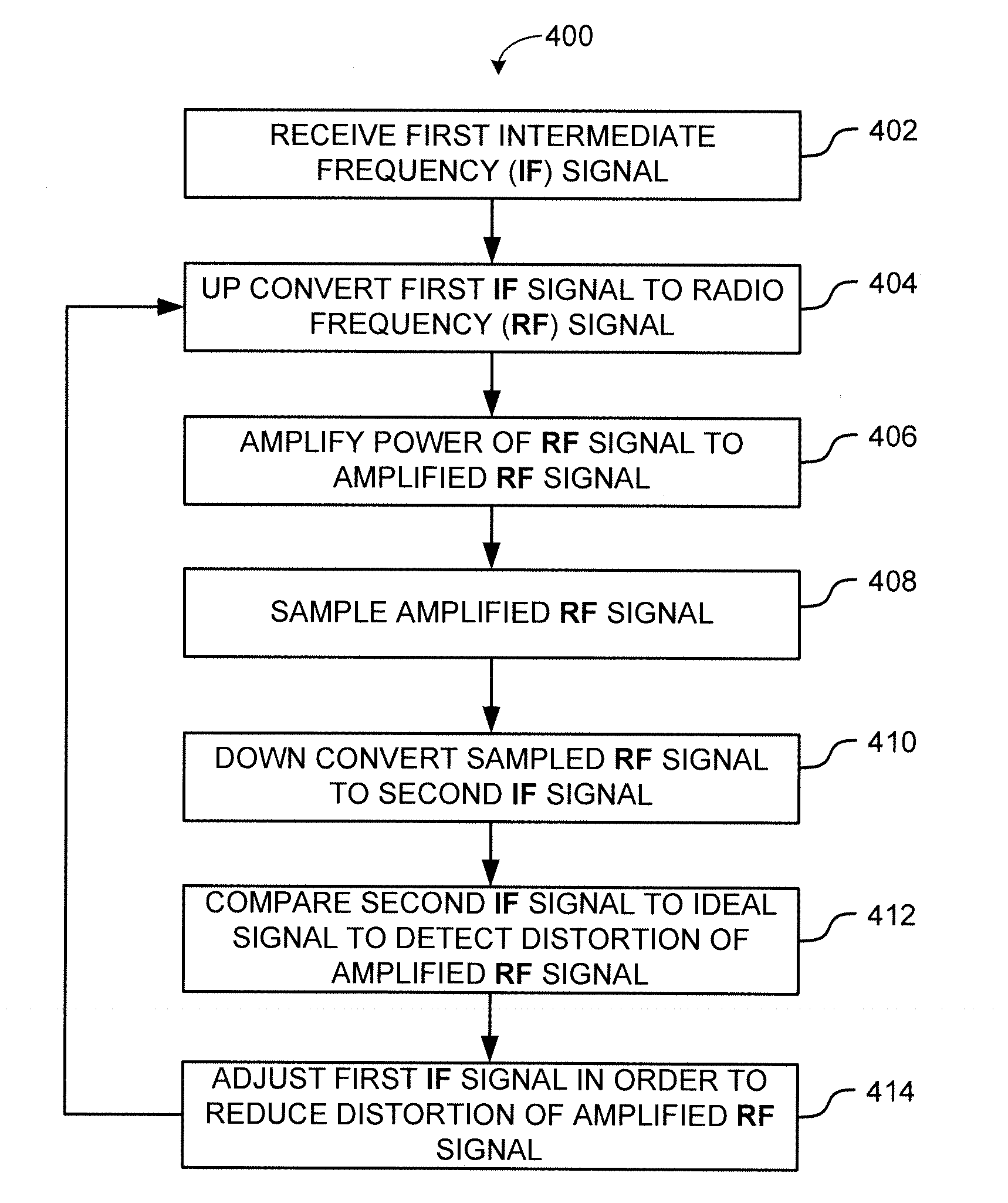
[0009]Various embodiments discussed herein provide systems and methods for improved linearization for radio frequency (RF) transmitters, which may also enable improved power yield for RF transmitters.
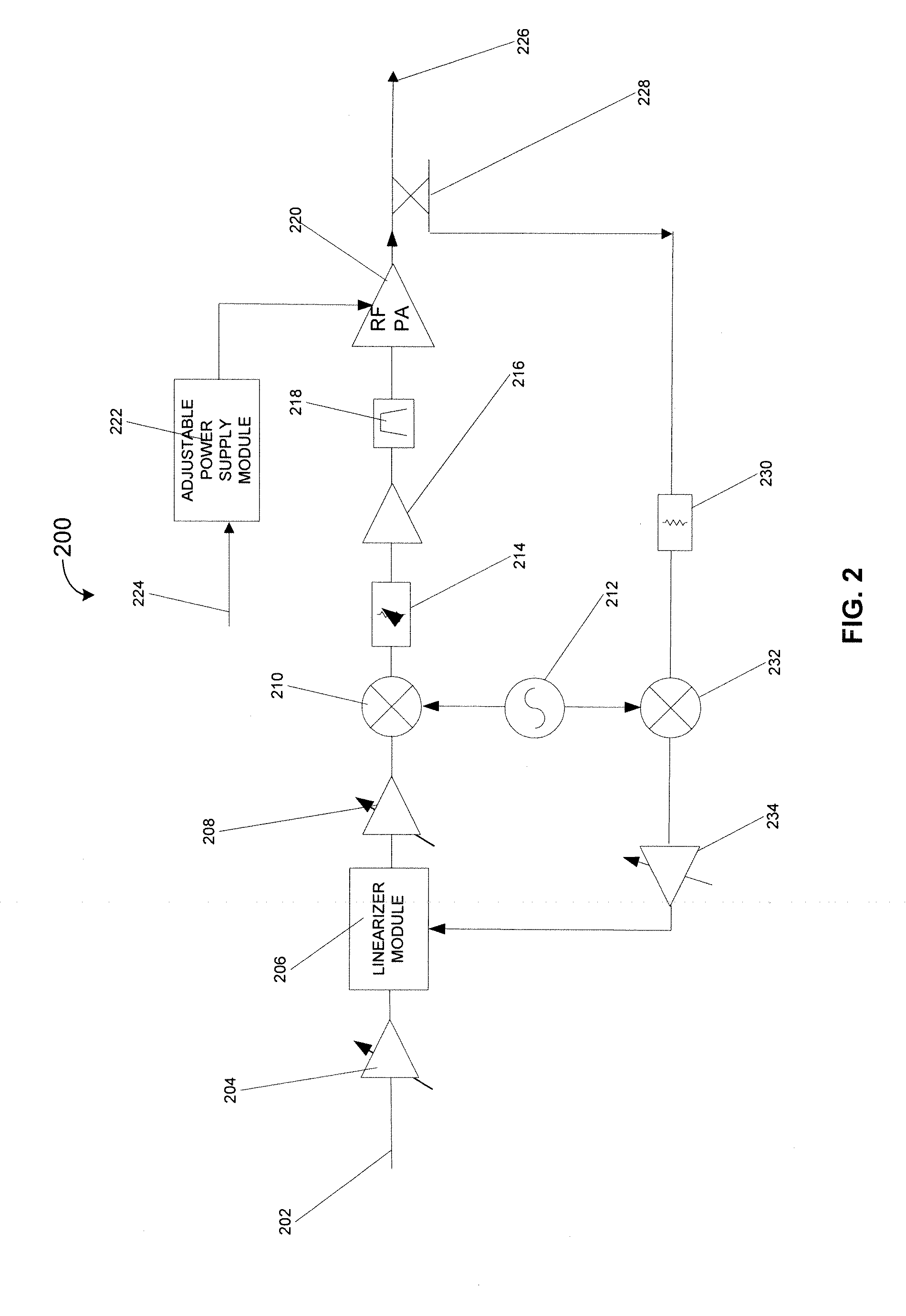
[0010]An exemplary system comprises a linearizer module, a first upconverter module, a power amplifier module, a signal sampler module, and a downconverter module. The linearizer module may be configured to receive a first intermediate frequency signal and to adjust the first intermediate frequency signal based on a reference signal and a signal based on the second intermediate frequency signal. The first upconverter module may be configured to receive and up-convert a signal based on the adjusted first intermediate frequency signal to a radio frequency signal. The power amplifier module may be configured to receive and amplify a power of a signal based on the radio frequency signal to an amplified radio frequency signal. The signal sampler module may be configured to sample a signal ba...
PUM
 Abstract
Description
Claims
Application Information