Prosthetic liner with proximal seal

a technology of prosthetic liner and proximal seal, which is applied in the field of prosthetic liner with proximal seal, can solve the problems of high degree of angular and torsional stress at the interface of the socket/liner and the residual limb, and achieve the effect of improving the efficiency of sealing the interstitial volume, efficient sealing, and efficient sealing

Active Publication Date: 2012-05-03
ALPS SOUTH EURO
View PDF0 Cites 23 Cited by
  • Summary
  • Abstract
  • Description
  • Claims
  • Application Information

AI Technical Summary

Benefits of technology

[0025]It should be noted that the quality of the foregoing seal has a dependence on the ability of the inner surface of the suspension sleeve to seal distally with the outer surface of the prosthetic socket at a circumferentially continuous region distal to the socket edge. The quality of the foregoing seal also depends on the ability of the suspension sleeve to seal proximally at a circumferentially continuous region proximal to the material leading edge. By “circumferentially continuous” is meant pertaining to an area which circumscribes. Thus, in general, the suspension sleeve must be long enough to simultaneously engage in both seals. Furthermore, the suspension sleeve must have the combination of physical dimensions such as unstretched and stretched circumferences and elastic dimensions such as elasticity, tensile strength, deformability, and the like to in order to create efficient seals. This is considered to be within the purview of the prior art. Furthermore, the efficiency of the seal depends on the quality of the contact between the suspension sleeve and the respective surfaces. In a preferred embodiment, the suspension sleeve comprises one material which forms a seal which can sustain a moderate vacuum in the range of from greater than 2 inches Hg to about 14 inches Hg. In other embodiments, the sleeve comprises a material differential from one end to the other end such that the overall efficiency o

Problems solved by technology

However, it had drawbacks which ultimately led to its supplantation by other methods.
One major drawback was the tendency of the residual limb to piston, or slip upwards and downwards in the interface upon ambulation.
The limited support resulted in a high degree of angular and torsional stress at the interface of the socket/liner and the residual limb.
As a result, the fit of the prosthesis changed with we

Method used


Image

  • Prosthetic liner with proximal seal
  • Prosthetic liner with proximal seal
  • Prosthetic liner with proximal seal

Examples


Embodiment Construction

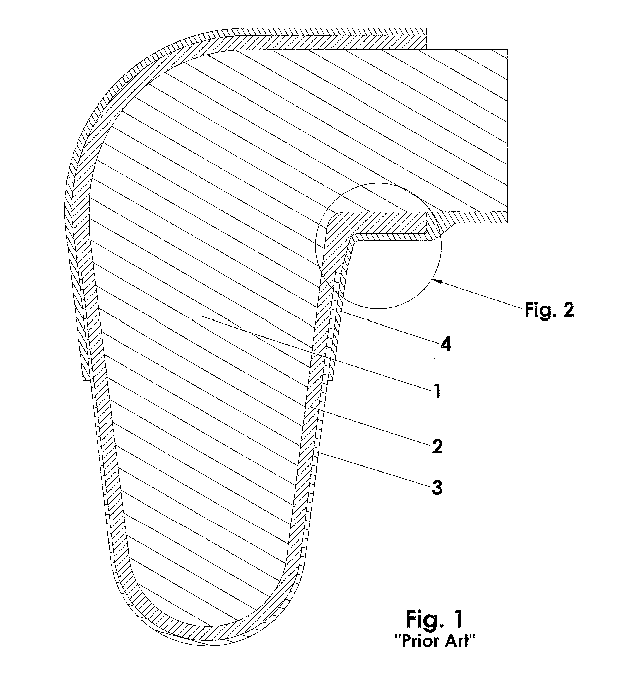
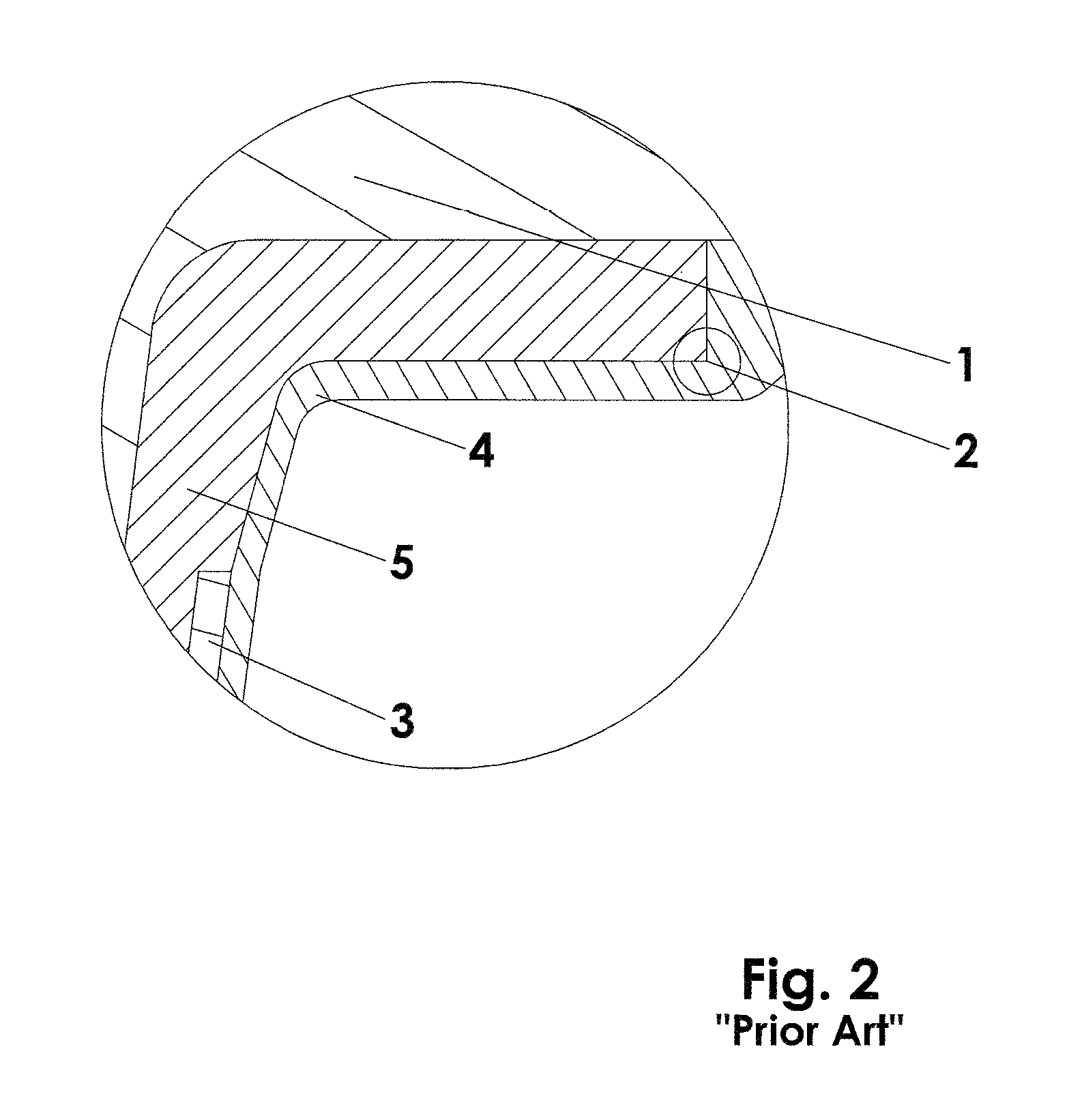
[0032]FIGS. 1 and 2 illustrate a prior art prosthetic assembly. The liner includes a fabric layer (2) into which a wearer's prosthetic limb (1) is inserted. The limb / liner combination is inserted into a prosthetic socket (3). The prosthetic socket (3) has a proximal portion adjacent an intermediate portion (5) of fabric layer (2), against which the distal portion of a suspension sleeve (4) can seal, and which extends proximally, to some extent, up beyond the proximal end (2′) of the fabric layer onto the residual limb (1). The suspension sleeve, in its proper functioning position, extends proximally from the socket, over the fabric liner, to the thigh of the patient, against which a seal is formed. A vacuum is established in the volume between the socket, the residual limb and the suspension sleeve.

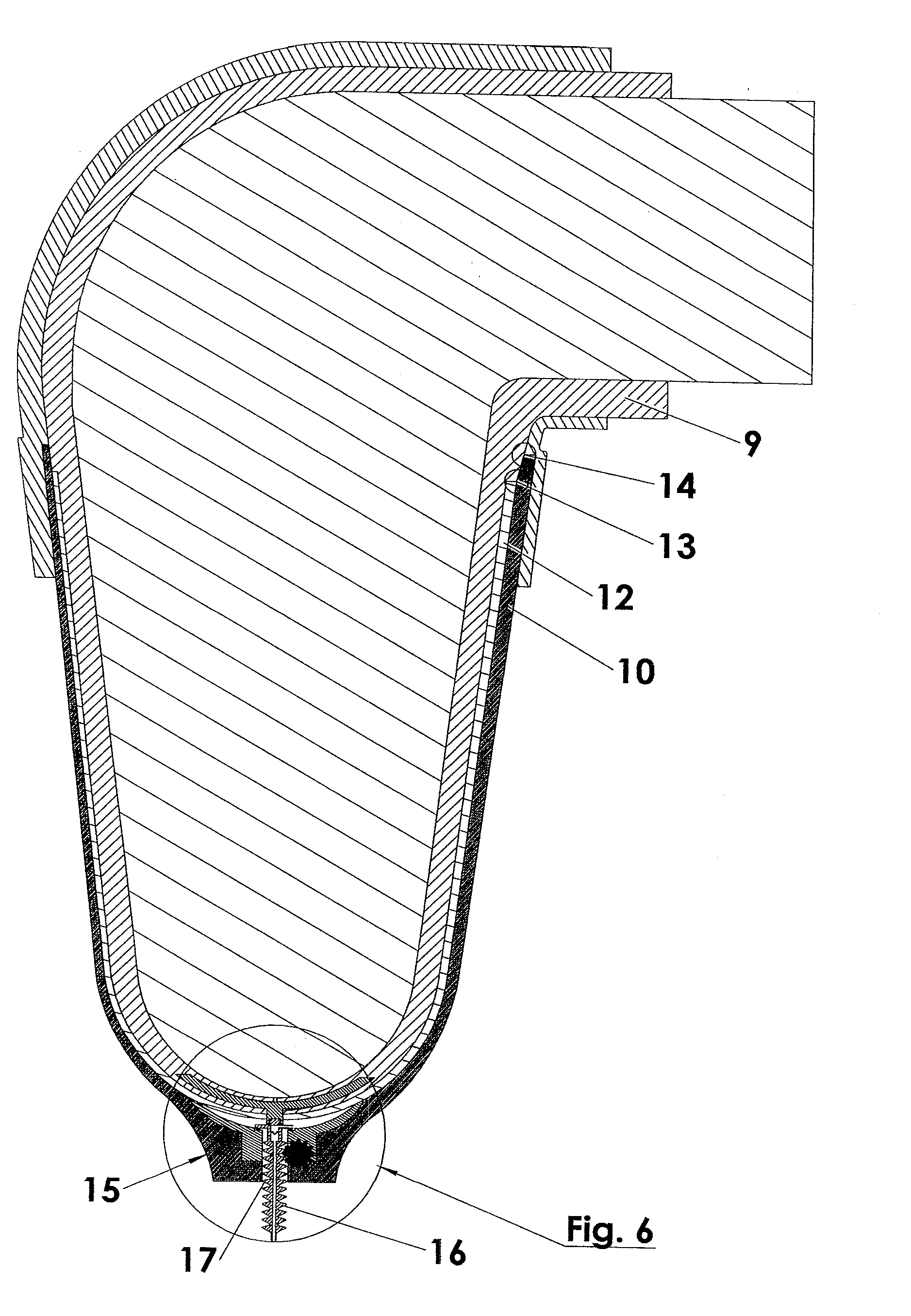
[0033]FIG. 3 is an illustration of an embodiment of a liner of the present invention comprising an elastomeric layer or interface layer (7), and a material layer (6) which overlies the di...


PUM


Abstract

A prosthesis suspension assembly comprising: a prosthetic socket having an open proximal end and a closed distal end and an interior surface complementally configured to a residual limb of an amputee, an interface or liner for receiving the residual limb and fittingly received in the socket, a distal outer surface of the liner comprises a porous or continuously cavitated, compressible material such as fabric and a proximal outer surface comprising an elastomeric material, a suspension sleeve which seals against the proximal outer surface of the liner and a proximal outer surface of the socket, and a locking pin connected to a distal end of the liner and lockingly retained in a hole in the distal end of the socket and including an air passage therethrough with a one-way valve therein for permitting the exit of air from an interstitial volume occupied buy said compressible material to atmosphere upon ambulation.

Description

PRIORITY[0001]This application is a Continuation-in-Part Application of U.S. application Ser. No. 12 / 381,146 filed on Mar. 6, 2009, which claims priority to U.S. provisional application Ser. No. 61 / 034,323, filed on Mar. 6, 2008.BACKGROUND OF THE INVENTION[0002]During the 1980's, a means of suspending a prosthesis was developed which consisted of a docking means fabricated into an interface which, in turn, was rolled onto the distal portion of the wearer's residual limb. The docking means engaged into the prosthesis, and the prosthesis was thereby locked in position of attachment to the patient's limb.[0003]Such a means of attachment became standard in the industry. However, it had drawbacks which ultimately led to its supplantation by other methods. One major drawback was the tendency of the residual limb to piston, or slip upwards and downwards in the interface upon ambulation. Over the years, it has been thought that pistoning occurred because only the distal portion of the limb ...

Claims


Application Information

Patent Timeline
IPC IPC(8): A61F2/80A61F2/78
CPCA61F2/7812A61F2/80A61F2002/5007A61F2002/5056A61F2002/7837A61F2002/7875A61F2002/805
Inventor LAGHI, ALDO A.
Owner ALPS SOUTH EURO
Why Eureka
Try Eureka