Target object processing method and target object processing apparatus

a processing method and target object technology, applied in glass making apparatus, manufacturing tools, manufacturing tools, etc., can solve the problems of reducing the efficiency of cutting substrates, affecting the quality of stacked portions, etc., to suppress the effect of light luminance reduction and efficient cutting substrates

Active Publication Date: 2012-05-10
QMC +1
View PDF8 Cites 47 Cited by
  • Summary
  • Abstract
  • Description
  • Claims
  • Application Information

AI Technical Summary

Benefits of technology

[0010]The present disclosure provides a target object processing method and a target object processing apparatus capable of suppressing generation of fine dust which may have a bad influence on element characteristics, preventing generation of an amorphous section on a surface of a substrate, and integrating a multiple number of stacked portions on a single wafer with high density.
[0011]Further, the present disclosure provides a target object processing method and a target object processing apparatus capable of processing a substrate without deteriorating element characteristics of the substrate.
[0013]Moreover, the present disclosure provides a target object processing method and a target object processing apparatus capable of controlling a laser beam emission intensity profile formed within a substrate or energy density of the laser beam by correcting an intrinsic divergence angle of the laser beam.
[0014]Besides, the present disclosure provides a target object processing method and a target object processing apparatus capable of efficiently cutting a substrate in a specific direction by controlling a shape and size of a laser beam, or a laser beam emission intensity profile or energy density of the laser beam.
[0015]Further, the present disclosure provides a target object processing method and a target object processing apparatus capable of providing a cut surface in good condition and suppressing a decrease in light luminance.

Problems solved by technology

However, in a conventional method, when the substrate is cut, fine dust may be generated, which may have a bad influence on element characteristics of the substrate.
Further, in the conventional method, a cut section of a relatively large area may be formed, and, thus, there has been a limit in integrating a multiple number of stacked portions on a single wafer with high density.
It is not easy to remove the adhering particles since they are solidified when cooled.
Consequently, the surface of the substrate may be uneven and the substrate may be cracked in unexpected directions when broken.
Particularly, a laser beam has its own divergence angle and there is a deviation in divergence angles even if the same kind of laser beam source is used, and, thus, it is difficult to form a spot appropriate for processing the inside of the substrate with a conventional laser beam transfer system.
In this cutting process, a considerable external force needs to be applied to the substrate, which results in an increase in the number of processes and processing time and causes an increase in costs.
Further, if the scribing process is not performed accurately, the substrate may be cracked in unexpected directions or a cut surface may have a defect in the cutting process.

Method used


Image

  • Target object processing method and target object processing apparatus
  • Target object processing method and target object processing apparatus
  • Target object processing method and target object processing apparatus

Examples


Embodiment Construction

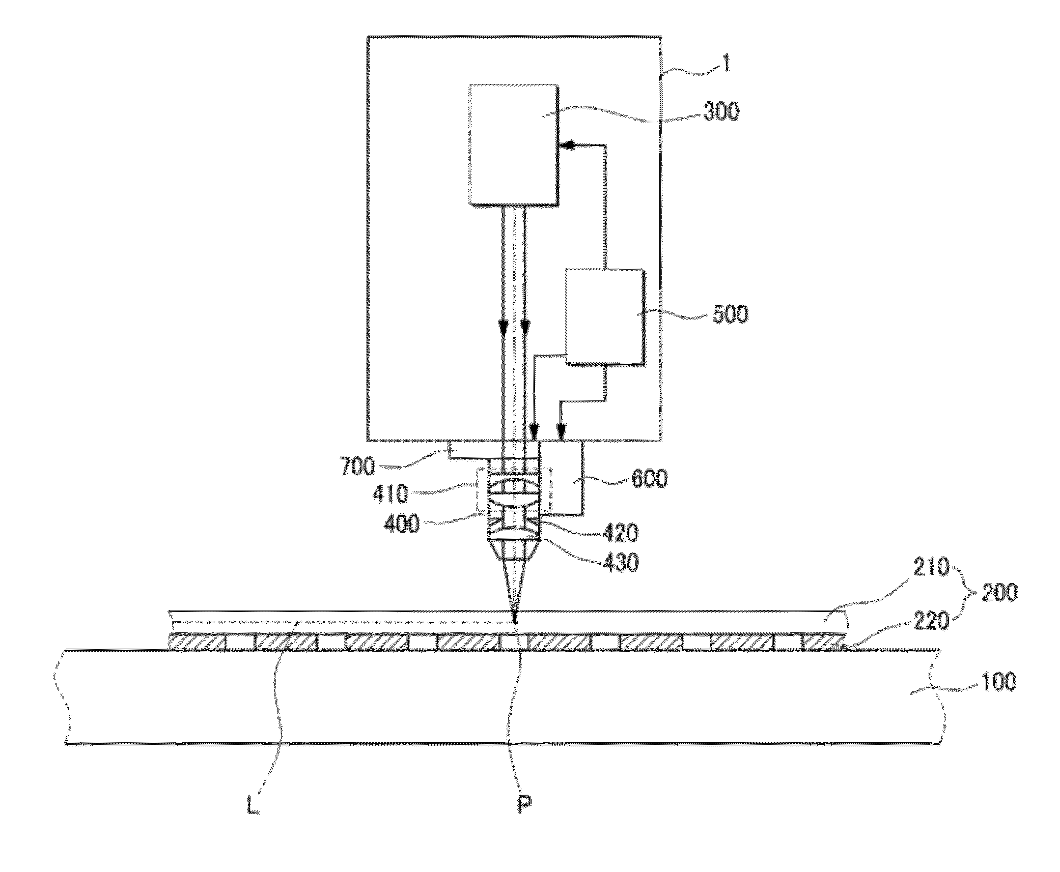
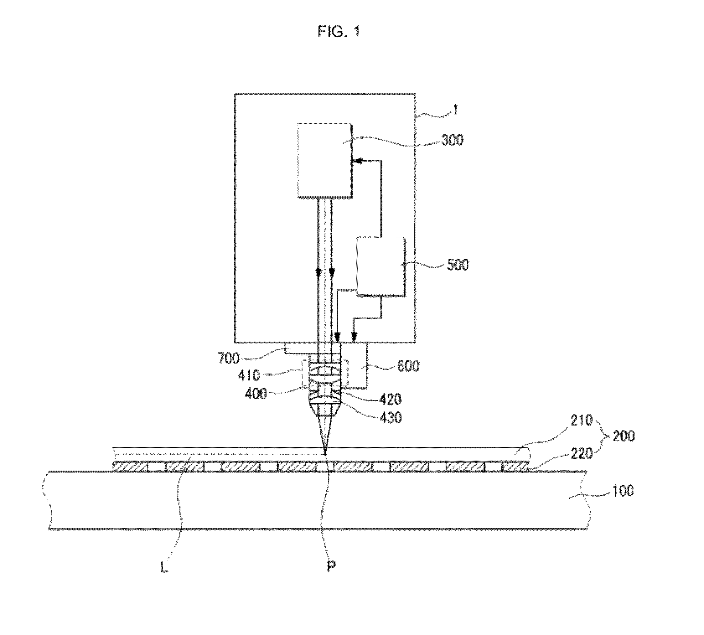
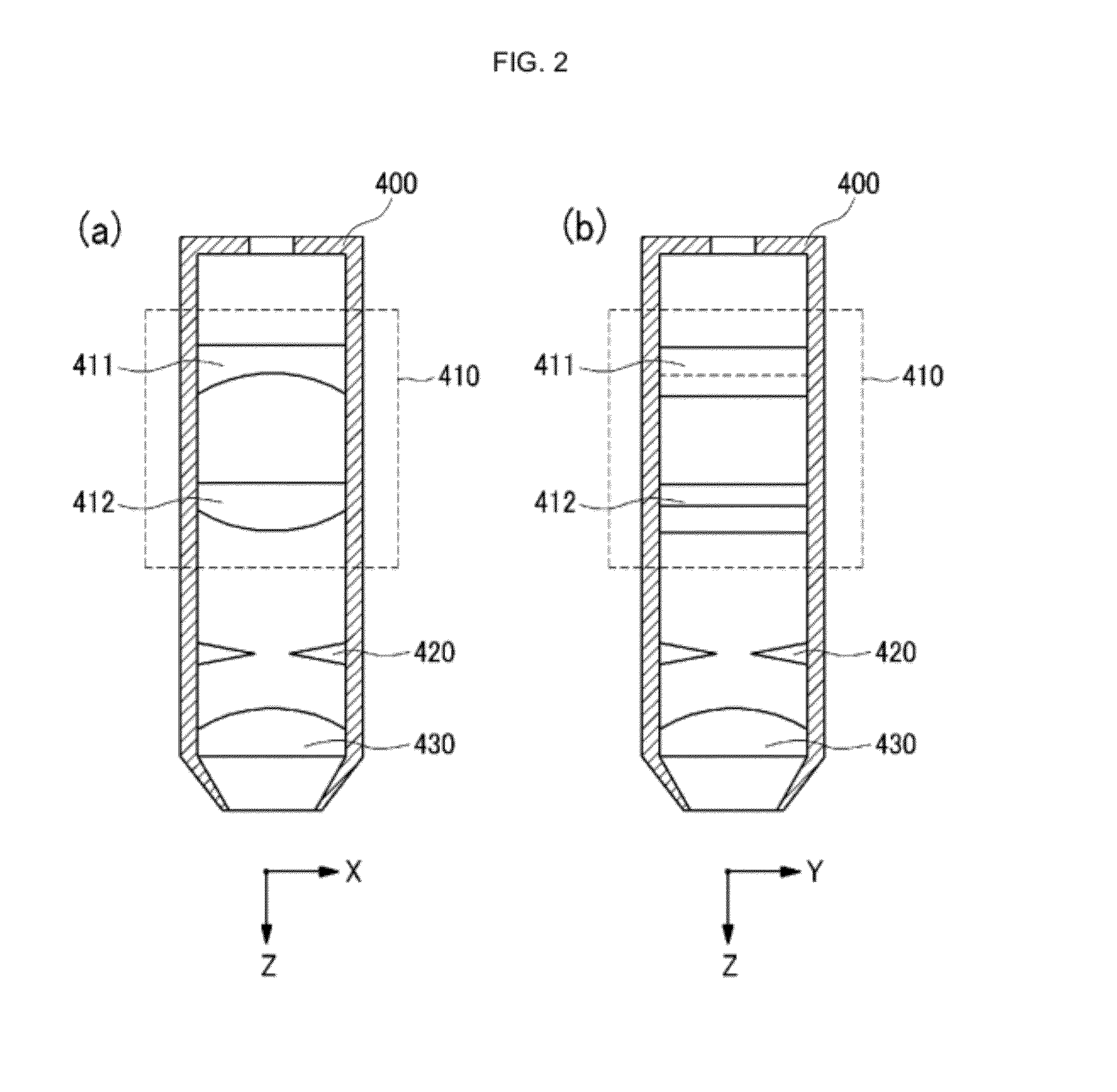
[0036]Hereinafter, embodiments of the present invention will be described in detail with reference to the accompanying drawings. However, it is to be noted that the present invention is not limited to the embodiments but can be realized in various other ways. In the drawings, parts irrelevant to the description are omitted for the simplicity of explanation, and like reference numerals denote like parts through the whole document.

[0037]Through the whole document, the term “connected to” or “coupled to” that is used to designate a connection or coupling of one element to another element includes both a case that an element is “directly connected or coupled to” another element and a case that an element is “electronically connected or coupled to” another element via still another element. Further, the term “comprises or includes” and / or “comprising or including” used in the document means that one or more other components, steps, operation and / or existence or addition of elements are n...


PUM

PropertyMeasurementUnit
divergence angleaaaaaaaaaa
self-breakingaaaaaaaaaa

Abstract

There is provided a target object processing method capable of self-breaking a target object with a laser beam. The target object processing method includes: generating a laser beam from a laser beam source; correcting a divergence angle of the generated laser beam; and forming a spot by condensing the corrected laser beam to the inside of the target object. A shape or a size of the spot is adjusted by correcting the divergence angle of the laser beam, a phase transformation area is formed within the target object by the spot, and the target object is subject to self-breaking with the phase transformation area as the starting point.

Description

[0001]This invention claims the priority benefit of Korean Patent Application No. 10-2010-0041077 filed on Apr. 30, 2010 is hereby incorporated by reference in its entirety.FIELD OF THE INVENTION[0002]The present disclosure relates to a target object processing method and a target object processing apparatus, and particularly relates to a target object processing method and a target object processing apparatus by using a laser beam for self-breaking the target object.BACKGROUND OF THE INVENTION[0003]Recently, as a laser technology advances, there has been used a method of scribing or cutting a target object such as a semiconductor substrate or a LED substrate using a laser beam for separating the target object into chips. Generally, in a scribing method using a laser beam, a scribing line is first formed on a substrate along a preset cut line by irradiating a laser beam to a surface of the substrate and the substrate is broken by a physical or thermal impact applied thereto.[0004]Ho...

Claims


Application Information

Patent Timeline
Patent Type & Authority Applications(United States)
IPC IPC(8): B28D1/00
CPCB23K26/0042B23K26/0057B23K26/0635B23K26/0648C03B33/091B23K26/0853B23K26/0869B23K2201/40C03B33/0222B23K26/0736B23K26/0006B23K26/0624B23K26/53B23K2101/40B23K2103/56
Inventor RYU, BENG SOLEE, BYONG SHIKJANG, HYEON SAMKIM, BUM JOONG
Owner QMC
Why Eureka
Try Eureka