
System and method for the identification of radiation in contaminated rooms

a radiation identification and radiation technology, applied in the field of system and method for the identification of radiation in contaminated rooms, can solve the problems of contaminating reactors, fuel and isotope processing facilities, and other rooms, and the conditions are often unknown in many of these facilities, and achieves low cost, convenient measurement and mapping in areas, and low cost. the effect of safety

Inactive Publication Date: 2012-05-10
SAVANNAH RIVER NUCLEAR SOLUTIONS
View PDF18 Cites 20 Cited by
  • Summary
  • Abstract
  • Description
  • Claims
  • Application Information

AI Technical Summary

Benefits of technology

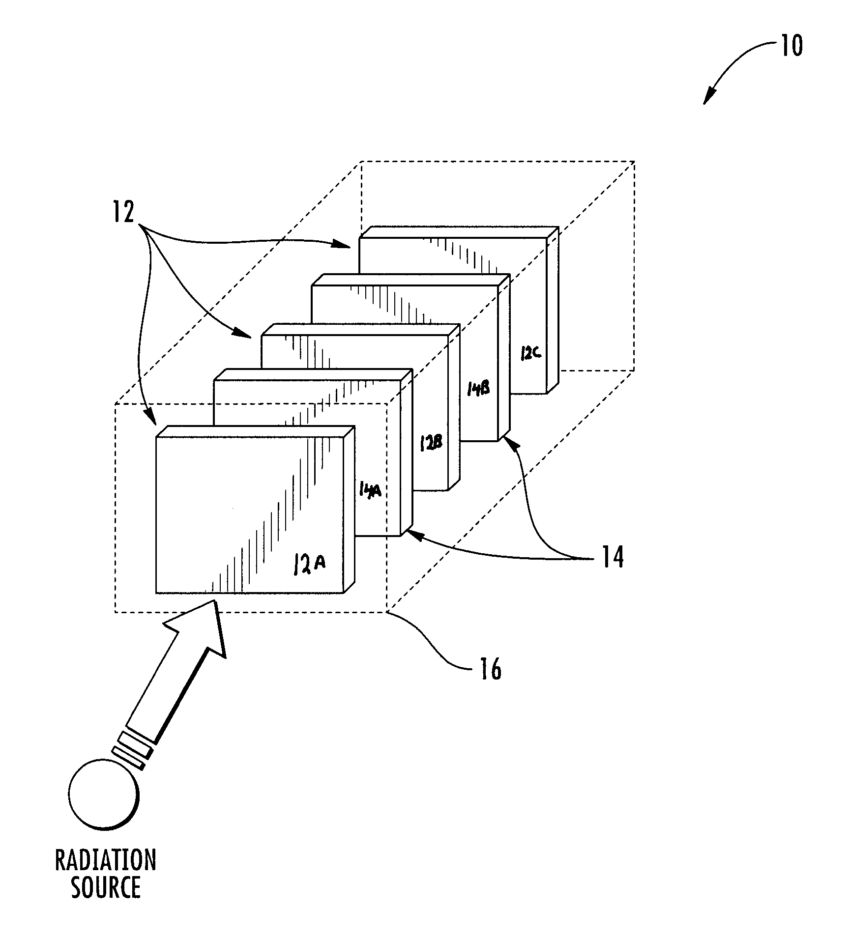
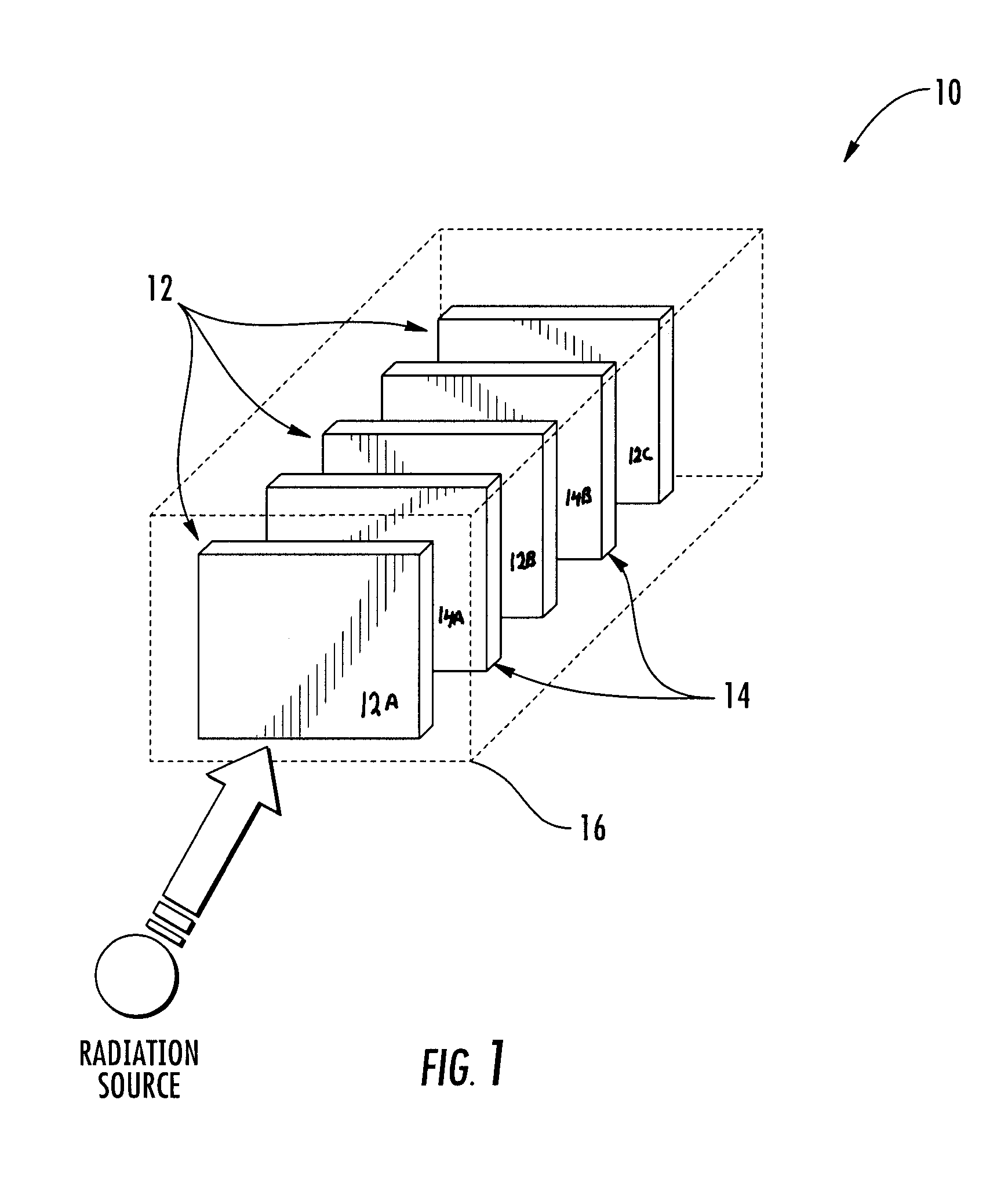
[0012]It is a further aspect of at least one of the present embodiments to provide for a radiation detector having a plurality of film layers positioned between opposing layers of radiation attenuation materials which can provide for a rapid screening tool for the detection and identification of one or more of a gamma-ray, alpha-particle and / or neutron emission source present in proximity to the detector.
[0032]It is a further aspect of at least one of the present embodiments to provide for a process of detection and identification of one or more of a gamma-ray, beta-particle, alpha-particle and / or neutron emission source present in a multi-surfaced environment in which information from a plurality of radiation detectors are used to provide a location and identity of radiation sources, the step of providing a location further including projection of the source information overlay onto the map or photograph of the examined room. Such apparatuses and processes facilitate an ability to provide 3D characterizations of the affected areas while having valuable properties that include low cost, robustness, and stability against falls, impacts, and extreme temperatures. In addition, the systems are remotely deployable during the measurement / characterization process and require no connecting power, communication cords or connection to other electronic devices. The portability, sensitivity and small size of the apparatus will facilitate the measurement and mapping in areas of a facility, which were previously considered physically inaccessible with traditional electrical-based radiation detection systems. An apparatus and process described herein offers an inexpensive and safer means to perform initial radiological characterizations, in-process surveys, and final status surveys to enable effective decontamination while minimizing exposures to workers.
[0033]This present invention relates further to a complete characterization of hot cells, gloveboxes, rooms and field locations contaminated with gamma-ray, alpha-particle, beta-particle, and neutron emitters by deploying a characterizer device, used to 1) locate the contaminated areas within a contaminated area, 2) identify / differentiate the radionuclide's in these areas, and 3) quantify the intensity of the contamination. The present invention also includes use of a an improved detector material that may be arranged into a stack or ‘sandwich’ which, if there are attenuating materials among the detector film / plates, can provide energy discrimination of the source. The invention further allows for a radiation detection apparatus that enables a full 360 degree top-to-bottom room characterization (4π-steradian field of view). This device takes advantage of the high sensitivity of the film / PSPs and provides a means of collimating the radiation that is detected to allow location determination.

Problems solved by technology

The use of radioactive material may result in the contamination of reactors, fuel and isotope processing facilities, laboratories, glove boxes, isolators, and other rooms.
These facilities are usually associated with extremely high dose rates and, therefore, it is imperative to use remote technologies for characterization and decommissioning to keep worker exposures as low as reasonably achievable in these highly contaminated environments.
These conditions are often unknown for many of these facilities.
Radiological and chemical contamination, as well as structural deterioration of such facilities presents risks to workers, which must be mitigated.
Although existing techniques are available for ascertaining the location and intensity of radiation contamination within a room, such techniques are subjective in nature, costly, not efficient, limited in application, not automatic, and inaccurate.

Method used


Image

  • System and method for the identification of radiation in contaminated rooms
  • System and method for the identification of radiation in contaminated rooms
  • System and method for the identification of radiation in contaminated rooms

Examples


Embodiment Construction

[0043]Reference will now be made in detail to embodiments of the invention, one or more examples of which are illustrated in the drawings. Each example is provided by way of explanation of the invention, and not meant as a limitation of the invention. For example, features illustrated or described as part of one embodiment can be used with another embodiment to yield still a third embodiment. It is intended that the present invention include these and other modifications and variations.

[0044]It is to be understood that the ranges mentioned herein include all ranges located within the prescribed range. As such, all ranges mentioned herein include all sub-ranges included in the mentioned ranges. For instance, a range from 100-200 also includes ranges from 110-150, 170-190, and 153-162. Further, all limits mentioned herein include all other limits included in the mentioned limits. For instance, a limit of up to 7 also includes a limit of up to 5, up to 3, and up to 4.5.

[0045]A radiatio...


PUM


Abstract

Devices and methods for the characterization of areas of radiation in contaminated rooms are provided. One such device is a collimator with a collimator shield for reducing noise when measuring radiation. The determination system uses a radiation detector comprising a plurality of overlapping layers of radiation sensitive film interspersed with adjacent layers of an attenuator material. The resulting sandwich of the stacked film layers and attenuator layers provides a useful detector. The detector can be used within a radiation detector apparatus having a collimator to enable a 360 degree field of view of radiation sources within a room or enclosed environment.

Description

CROSS REFERENCE TO RELATED APPLICATION[0001]This application claims the benefit of U.S. application Ser. No. 61 / 411,753 filed on Nov. 9, 2010 and entitled, “Hot Cell / Glovebox Characterization Using FRID™, RadCrystal™, and GrayQb.” U.S. application Ser. No. 61 / 411,753 is incorporated by reference herein in its entirety for all purposes.[0002]This application relates to PCT / US11 / 38250 filed Aug. 18, 2011 entitled “System and Method for the Identification of Radiation in Contaminated Rooms” and which is incorporated herein by reference.STATEMENT AS TO RIGHTS TO INVENTIONS MADE UNDER FEDERALLY SPONSORED RESEARCH AND DEVELOPMENT[0003]This invention was made with Government support under Contract No. DE-AC09-08SR22470 awarded by the United States Department of Energy. The Government has certain rights in the invention.FIELD OF THE INVENTION[0004]The present invention relates generally to the characterization of areas such as shielded cells (hot cells), glove boxes, and rooms contaminated ...

Claims


Application Information

Patent Timeline
Patent Type & Authority Applications(United States)
IPC IPC(8): G01T1/08G01T1/02
CPCG01T7/00G01T1/08
Inventor COLEMAN, JODY RUSTYNFARFAN, EDUARDO B.
Owner SAVANNAH RIVER NUCLEAR SOLUTIONS
Learn More