Electric machine and method for manufacturing it

a technology of electric motors and stators, which is applied in the direction of dynamo-electric machines, electrical apparatus, magnetic circuits, etc., can solve the problems of difficult to make effective electrical connections between electronic circuitry and motors, easy to be subject to reliability and efficiency problems,

Active Publication Date: 2012-05-10
SPAL AUTOMOTIVE
View PDF9 Cites 4 Cited by
  • Summary
  • Abstract
  • Description
  • Claims
  • Application Information

AI Technical Summary

Benefits of technology

[0015]Another aim of the invention is to propose a stator, in particular for an electric motor with built-in electronic circuitry where the excess heat produced by the circuitry itself is effectively absorbed.
[0016]A further aim of the invention is to propose a stator for an electric machine with a reliable electrical connection between the electric motor and the electronic power circuitry.

Problems solved by technology

In the case of electric motors with built-in electronic circuitry, absorption of excess heat is not easy to achieve because it is difficult to make an effective electrical connection between the electronic circuitry and the motor and good thermal contact between the electronic circuitry and a corresponding heat sink, in particular the cover.
The main problems are due precisely to the fact that, because the casing has to be closed with the cover, it is difficult, with the motor substantially closed, to make all the electrical and mechanical connections in optimum manner.
To enable the assembly to be closed, prior art solutions provide at least one sliding contact, such as a connector, for example, which is easily subject to problems of reliability and efficiency for example on account of vibrations, contact wear, or operating temperature, between the motor and the electronic circuitry or between the electronic circuitry and the terminal strip.
In the second case, the electronic circuitry is effectively and rigidly connected to the motor, for example by soldering, whilst the contact of the circuitry with the cover is not particularly effective in terms of heat exchange on account of the necessary closing tolerances.
Thus, in the latter solution, the electronic circuitry is not effectively pressed against the heat sink, for example on account of assembly tolerances.
Also, as already mentioned, there is normally a sliding contact, with all its inherent limitations, between the electronic circuitry and the terminal strip on the outside.

Method used


Image

  • Electric machine and method for manufacturing it
  • Electric machine and method for manufacturing it
  • Electric machine and method for manufacturing it

Examples


Embodiment Construction

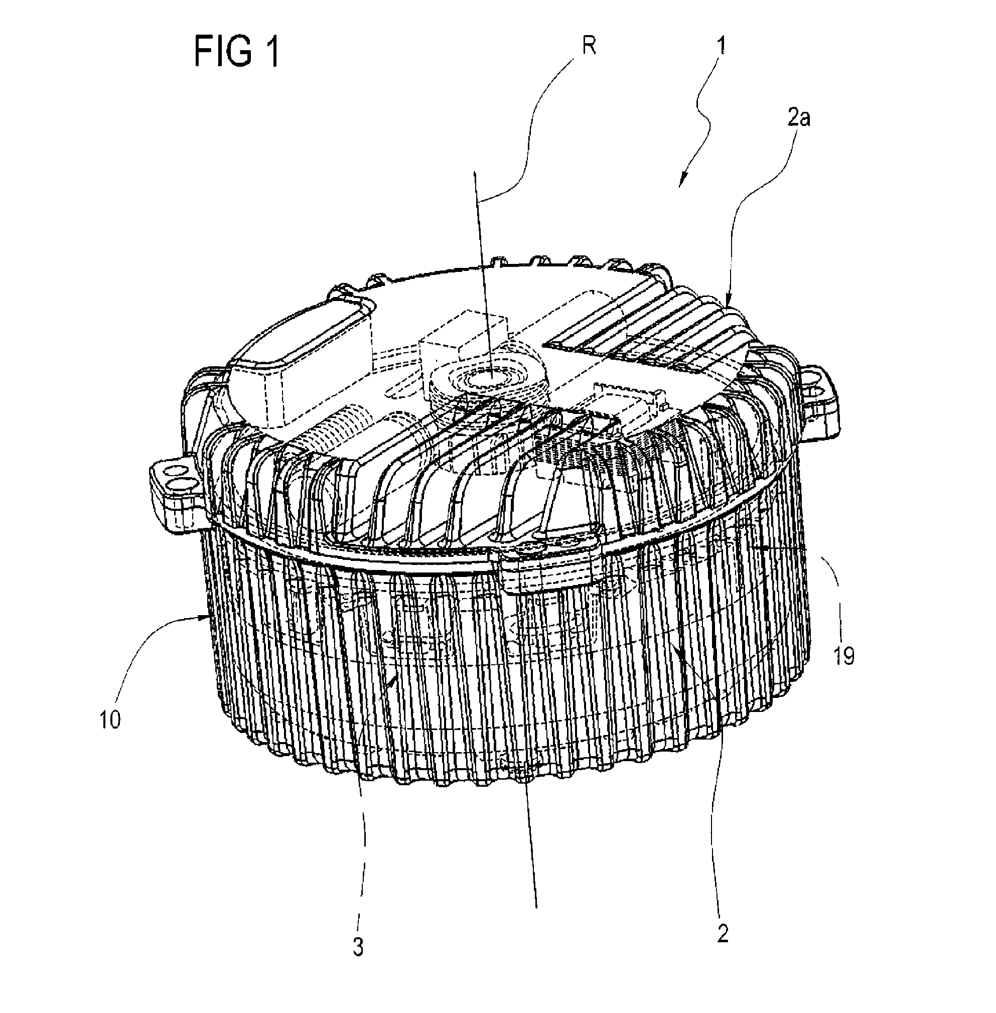
[0036]With reference to the accompanying drawings and in particular with reference to FIGS. 1 and 5, the numeral 1 denotes an electric machine made using the method according to this invention.

[0037]The machine 1 comprises an electric motor of the sealed type, that is to say without any opening giving access to the inside of it, to which this specification expressly refers but without limiting the scope of the invention.

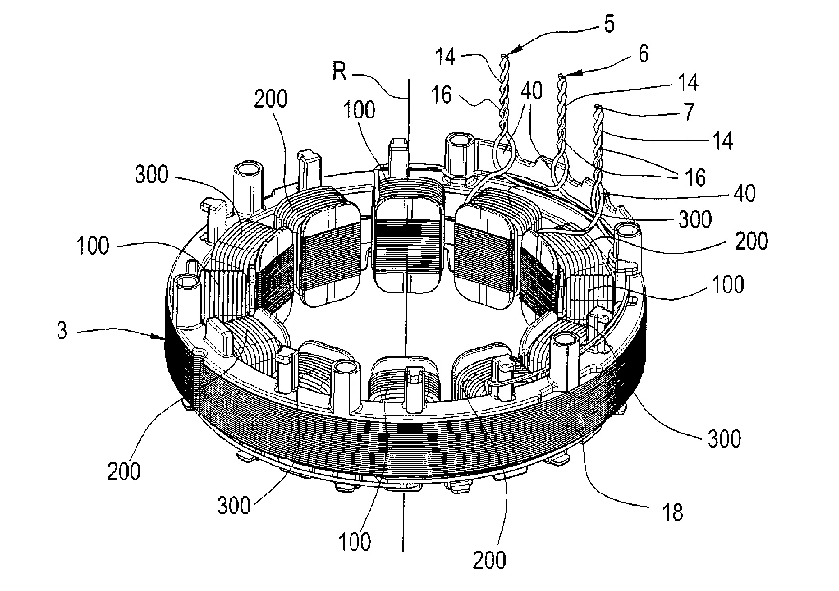
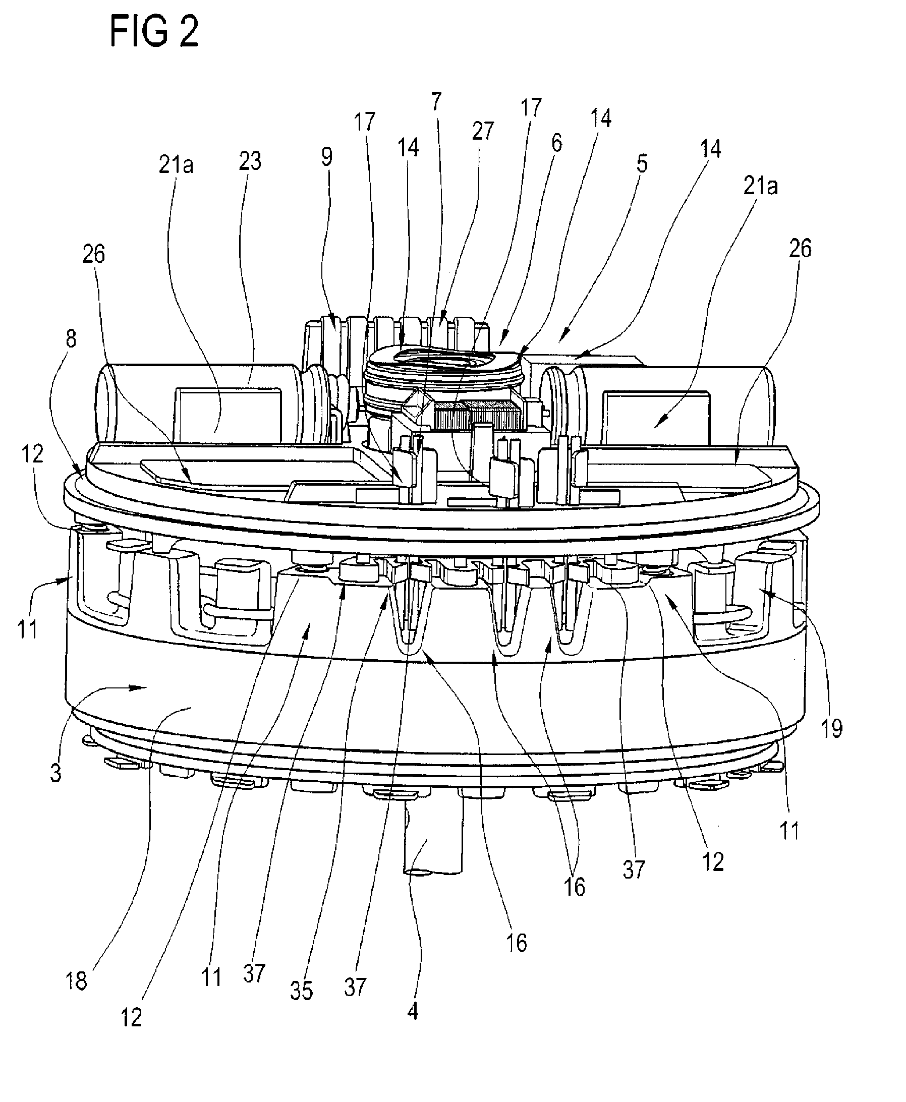
[0038]The machine 1 comprises a casing 2 and a respective cover 2a which together form a sealed enclosure 10, a stator or stator unit 3 housed in the casing; and a rotor or rotor unit 4, housed in the casing 2 and rotatably connected to the latter.

[0039]With reference in particular to FIGS. 2 and 4, the stator 3, in the example illustrated, has three electric terminations 5, 6, 7 and the machine 1 comprises an electronic circuit 8 for powering the electric terminations 5, 6, 7. More in detail, the machine illustrated in particular in FIGS. 9a and 9b comprises twelve ...


PUM

PropertyMeasurementUnit
lengthaaaaaaaaaa
lengthaaaaaaaaaa
lengthaaaaaaaaaa

Abstract

A method for making a rotary electric machine comprises the steps of: preparing a core (18) having a plurality of pole expansions and a plurality of windings (100, 200, 300) made of electrically conductive material on the pole expansions, where at least a part of the windings (100, 200, 300) is made from a conductor wire having a free end (14) that can be connected electrically to a mains power supply; stably coupling to each other at least two free ends (14) of different windings (100, 200, 300) so as to connect them to a single power supply terminal; twisting the coupled ends (14) together to form a single electrical termination (5, 6, 7) twisted along a principal line of extension of the electrical termination (5, 6, 7).

Description

TECHNICAL FIELD[0001]This invention relates to a stator for an electric motor and to a method for making the electric windings of the motor, the stator being preferably intended for use in an electric machine of the type having the electronic control circuitry built into it. More specifically, this invention relates to a method for making the stator of an electric motor.BACKGROUND ART[0002]A rotary electric machine basically comprises a casing, a stator rigidly connected to the casing, a rotor, for example of the type with permanent magnets, enclosed by the casing and rotatably connected to the latter.[0003]When the electric machine functions as a motor, the rotor is rotationally driven by powering the stator through an electronic circuit or control circuitry, which in this case, is also positioned inside the casing.[0004]The casing is then closed by a cover with a terminal strip on the outside of it to power the electronic circuitry and, hence, the electric motor. The electronic dr...

Claims


Application Information

Patent Timeline
Patent Type & Authority Applications(United States)
IPC IPC(8): H02K3/28H02K15/00
CPCH02K3/522H02K11/0073H02K15/0075Y10T29/49009H02K15/0087H02K15/02H02K2203/06H02K15/0068H02K11/33H02K1/2706
Inventor DE FILIPPIS, PIETRO
Owner SPAL AUTOMOTIVE
Why Eureka
Try Eureka