
Method and apparatus for high precision spectroscopy

a high-precision spectroscopy and apparatus technology, applied in the field of high-precision spectroscopy, can solve the problems of wide transition line shapes, inconvenient precision measurements, induced anisotropy, etc., and achieve the effect of improving contrast and minimizing the geometrical dimensions of the apparatus

Inactive Publication Date: 2012-05-10
BEN GURION UNIVERSITY OF THE NEGEV
View PDF2 Cites 40 Cited by
  • Summary
  • Abstract
  • Description
  • Claims
  • Application Information

AI Technical Summary

Benefits of technology

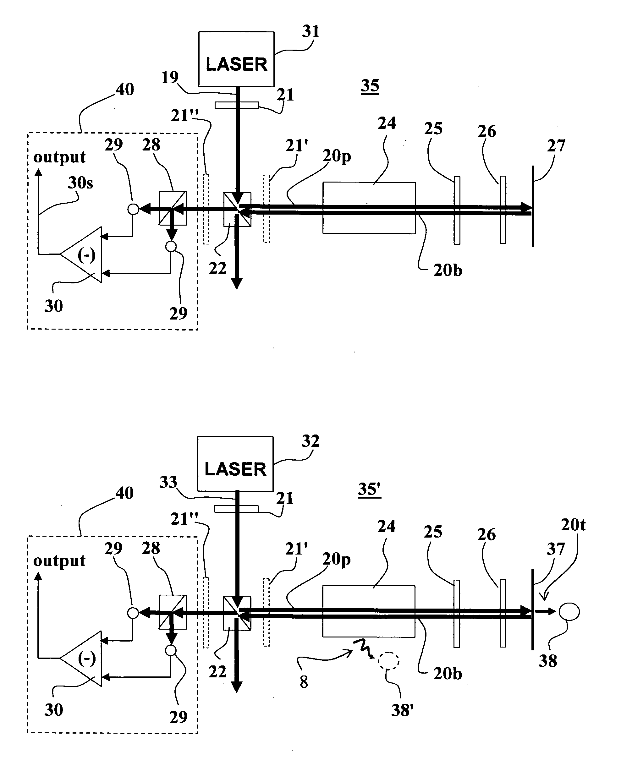
[0025]The present invention provides a methods and apparatuses for Doppler-free polarization spectroscopy, that enables perfect pump-probe beams overlap, and that substantially miniaturize the apparatus geometrical dimensions. The Doppler-free polarization spectroscopy apparatuses of the invention can be further utilized to measure magnetic fields intensities using NMOR, and with some modifications to measure CPT signals with relatively improved contrast.
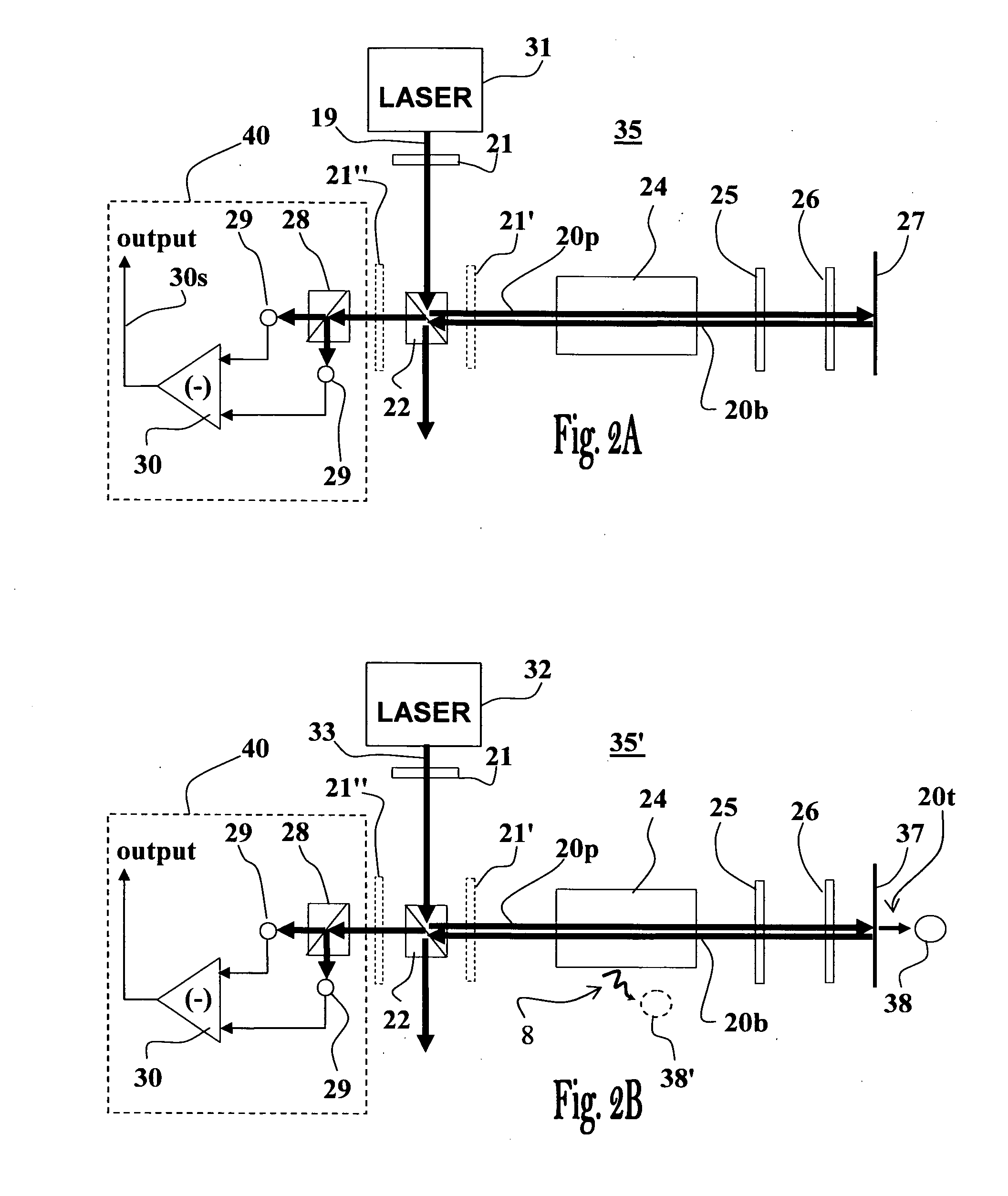
[0030]This preferred embodiment may be easily modified to further allow measurement of CPT signals by employing a frequency modulated laser beam as the input beam, and by implementing the optical reflecting means by means of a semi-transparent mirror, thereby allowing a fraction of the intensity of the beam hitting it to pass through it in the direction of a third photodetector placed therebehind and adapted for CPT signals measurements (CPT measurements by absorbance). Alternatively or additionally, an additional photodetector may be positioned adjacent the vapor cell containing the sample and adapted for fluorescence detection for coherent population trapping measurements (CPT measurements by fluorescence).
[0039]In this way portion of the beam received in the optical means after passage through the vapor cell is reflected back towards the vapor cell through a first phase retarding elements (i.e., the phase retarding element disposed between the vapor cell and the semi transparent optical reflection element). The double trip through the first phase retarding element (first passage in the beam arriving from the vapor cell and second passage in the reflected beam) circularly polarizes the retro reflected pump beam. The portion of the incident beam that passes through the semi transparent optical reflection element towards the polarimeter passes through the second phase retarding element (i.e., the phase retarding element disposed between the semi transparent optical reflection element and the polarimeter), which cancels phase retardations induced by the first phase retarding element, which thus becomes linearly polarized. The polarimeter signal may be applied for laser frequency lock or for measuring NMOR signals.

Problems solved by technology

In high precision spectroscopy measurements the Doppler broadening (spectral lines broadening due to velocity distribution of the particles) is a problem resulting in wide transition line shapes, which are usually too broad and thus not suitable for precision measurements.
This circularly polarized pump beam polarizes the sample, resulting in induced anisotropy.
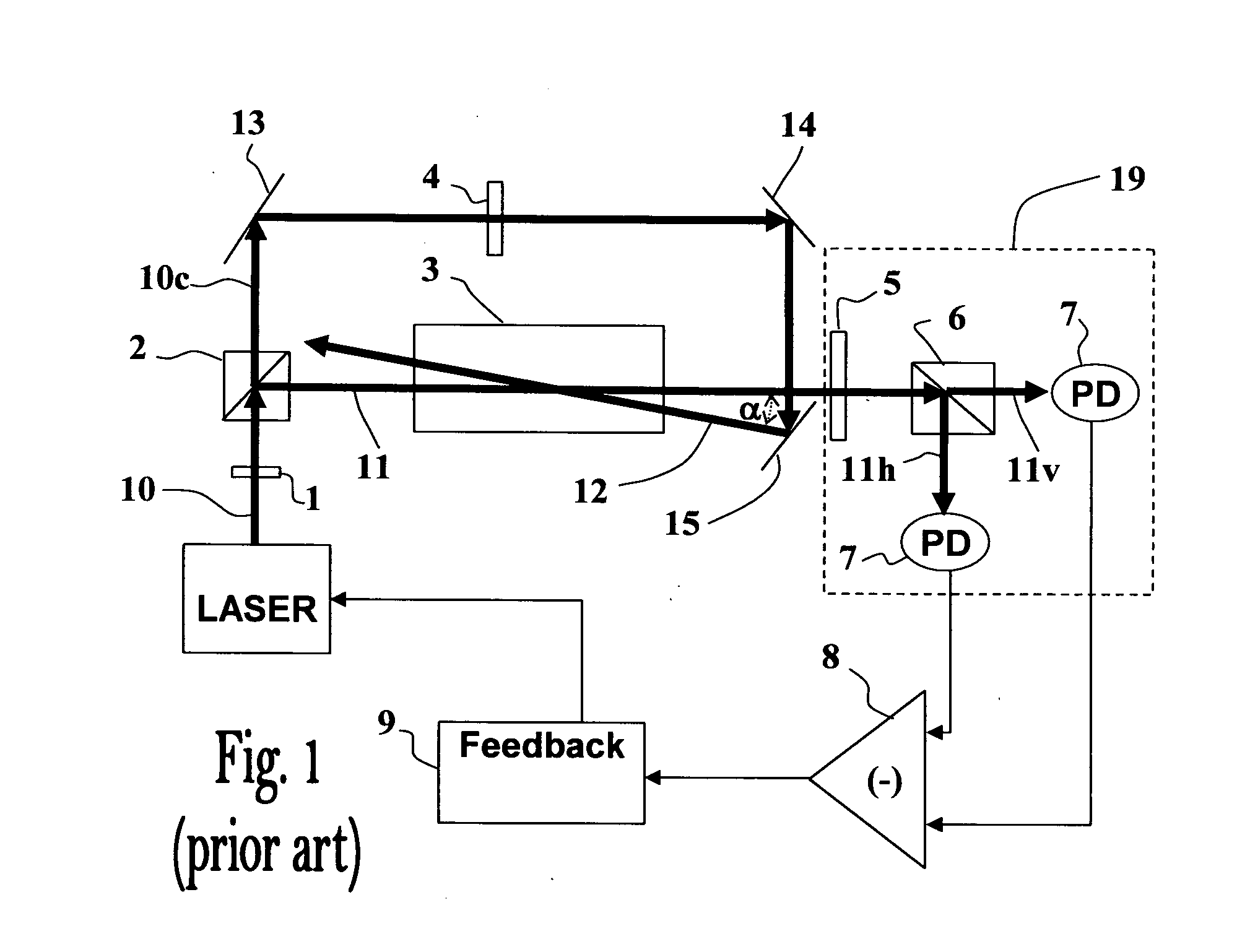
However, as seen in FIG. 1, the pump and probe beams nearly overlap, and inherently, it is not possible to perfectly overlap the pump and probe beams in such conventional polarization spectroscopy setups since there will always be an angle of α degrees between them, which spoils measurements precision.
These prior art Doppler-free configurations do not enable perfect overlap between the pump beam and the probe beam.
Such a configuration is not ideal for miniaturization and alignment.
Additional difficulties arising in such conventional spectroscopy setups are due to the multiple mirror elements comprised therein that require careful alignment, and thus complicates the assembly of devices based on it.
However, in most cases where NMOR is performed in a pump-probe fashion the beams are perpendicular to each other [Kominis et al., Nature, 422, 596 (2003)], hence the sensitivity is limited by the intersection volume of the beams.
Furthermore, in the common pump-probe NMOR setups, in which the beams are perpendicular to each other, it is necessary to have optical access to the vapor cell from two directions which present a difficulty when considering scalability in applications requiring array of such pump-probe NMOR cells (e.g., magnetic imaging).
The approaches described above do not provide satisfactory solutions for high precision Doppler-free spectroscopy.

Method used


Image

  • Method and apparatus for high precision spectroscopy
  • Method and apparatus for high precision spectroscopy
  • Method and apparatus for high precision spectroscopy

Examples


Embodiment Construction

[0057]The present invention provides a method and apparatus for retro-reflecting Doppler-free polarization spectroscopy, enabling substantially improved overlapping of pump and probe beams, improved precision of the measured signals, and miniaturization of the apparatus. The present invention further provides optical polarization spectroscopy setups suitable for measuring magnetic fields by NMOR and for CPT measurements.

[0058]With reference to FIG. 2A, showing an optical arrangement of apparatus 35 of the invention, also referred to hereinafter as the “T” shape configuration, comprising an input light beam 19 provided by a laser source 31 which is conventionally capable of producing a linearly polarized laser beam. The apparatus 35 includes a phase retarding element 21 used for circularly or elliptically polarizing the input beam 19. Apparatus 35 also includes a non-polarizing splitting element 22 (e.g., NPBS—non-polarizing beam splitter), enabling directing portion of the beam ente...


PUM


Abstract

The invention provides spectroscopy apparatuses and methods allowing precise overlapping between circularly polarized pump beam and a counter propagating linearly polarized probe beams in a sample which presents unique advantages for precision spectroscopy. In general, the apparatus comprises a phase retarding element with which by double pass by retro reflection of an incident beam turn linearly polarized light to circular and vice versa. This unique configuration enable to design a compact and miniature apparatus which may be applied for measuring polarization spectroscopy, nonlinear optical rotation and coherent population trapping phenomena with certain advantages resulting from the unique optical arrangement. The design of the apparatus further facilitates integration and scaling to produce arrays of units which may be particularly useful for magnetometry applications. Other important applications of the invention include laser frequency stabilization and atomic clocks.

Description

Field of the Invention[0001]The present invention relates to high precision spectroscopy, and more particularly to a method and apparatus utilizing polarization spectroscopy, nonlinear magneto optical rotation and coherent population trapping for detecting Doppler-free spectral features with high precision.BACKGROUND OF THE INVENTION[0002]In high precision spectroscopy measurements the Doppler broadening (spectral lines broadening due to velocity distribution of the particles) is a problem resulting in wide transition line shapes, which are usually too broad and thus not suitable for precision measurements. In order to resolve the naturally narrow spectral features that are hindered by this broad profile it is common to use a spectroscopy configuration employing two counter propagating laser beams.[0003]Polarization spectroscopy is a known Doppler-free experimental technique utilized in high precision spectroscopy. It was first demonstrated by Wieman and Hänsch in 1976 [Wieman and H...

Claims


Application Information

Patent Timeline
IPC IPC(8): G01J4/00
CPCG01J3/447G01N21/1717G01N2021/218G01N2021/1727G01N21/23
Inventor GROSWASSER, DAVID
Owner BEN GURION UNIVERSITY OF THE NEGEV
Learn More