Imaging system with automatically engaging image stabilization

a technology of image stabilization and imaging system, which is applied in the field of imaging systems, can solve the problems of reducing affecting the quality of the image, so as to reduce the waste of energy, prolong the battery life, and reduce the power consumption of the imaging system

Inactive Publication Date: 2012-05-10
APPLE INC
View PDF1 Cites 15 Cited by
  • Summary
  • Abstract
  • Description
  • Claims
  • Application Information

AI Technical Summary

Benefits of technology

[0027]An advantage of the present invention is that the power consumption of the imaging system is reduced when the image stabilization system is disengaged, thereby extending battery life and reducing wasted energy.
[0028]An additional

Problems solved by technology

If motion of the image capture device or the scene occurs during image capture, motion blur can result in the captured image as the magnitude of the motion increases relative to the exposure time.
Global motion blur is produced when the image capture device is moving relative to the scene during capture, resulting in the entire image being blurred.
Motion blur problems are generally more severe in low light level photography environments due to the fact that longer exposure times are typically required.
None of the above-described methods are effective to reduce the effects of local motion blur.
High-grade optical elements with large apertures and image sensors with larger pixels are substantially more expensive, and are therefore not practical for many applications.
However, flash photography is typically only useful if the distance between the flash and the scene being photographed is relatively small.
Flash photography also tends to produce artifacts such as red

Method used


Image

  • Imaging system with automatically engaging image stabilization
  • Imaging system with automatically engaging image stabilization
  • Imaging system with automatically engaging image stabilization

Examples


Embodiment Construction

[0034]In the following description, a preferred embodiment of the present invention will be described in terms that would ordinarily be implemented as a software program. Those skilled in the art will readily recognize that the equivalent of such software can also be constructed in firmware or hardware. Because image manipulation algorithms and systems are well known, the present description will be directed in particular to algorithms and systems forming part of, or cooperating more directly with, the system and method in accordance with the present invention. Other aspects of such algorithms and systems, and hardware or software for producing and otherwise processing the image signals involved therewith, not specifically shown or described herein, can be selected from such systems, algorithms, components and elements known in the art. Given the system as described according to the invention in the following materials, software not specifically shown, suggested or described herein ...


PUM


Abstract

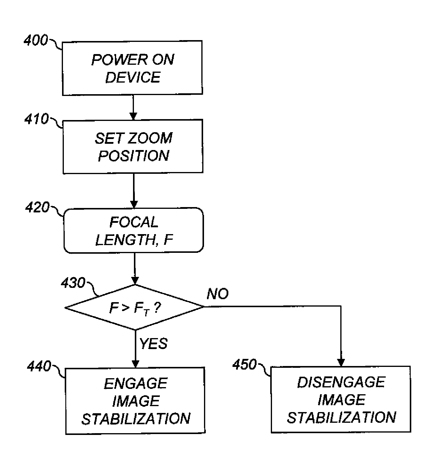
An image stabilized imaging system, comprising a variable magnification optical system for imaging a scene; an image stabilization system; a user control for controlling the magnification of the variable magnification optical system; and a processor. The processor is used to perform the steps of determining a user-controlled magnification setting of the variable magnification optical system; and selectively engaging the image stabilization system responsive to the determined magnification setting.

Description

CROSS REFERENCE RELATED APPLICATION[0001]Reference is made to commonly assigned, U.S. patent application Ser. No. ______ (Docket 96183), filed ______, by Noah J. Stupak, et al., entitled “Automatic Engagement of Image Stabilization”, which is incorporated herein by reference.FIELD OF THE INVENTION[0002]This invention pertains to the field of imaging systems and more particularly imaging systems having a selectively engaged image stabilization system.BACKGROUND OF THE INVENTION[0003]An electronic imaging system depends on a lens system to form an image on an image sensor to create an electronic representation of a visual image. Examples of such image sensors include charge coupled device (CCD) image sensors and active pixel sensor (APS) devices. (APS devices are often referred to as CMOS sensors because of the ability to fabricate them in a Complementary Metal Oxide Semiconductor process.) A sensor includes a two-dimensional array of individual picture element sensors, or “pixels.” F...

Claims


Application Information

Patent Timeline
IPC IPC(8): G02B27/64
CPCH04N5/2328H04N5/23248H04N23/68H04N23/685
Inventor KARN, KEITH S.STUPAK, NOAH J.WHITE, TIMOTHY J.
Owner APPLE INC
Why Eureka
Try Eureka