Heat-assisted magnetic recording medium and magnetic storage device

a technology of which is applied in the field of heat-assisted magnetic recording medium and magnetic storage device, can solve the problems of inability to meet the requirements of writing, deterioration of thermal stability, and tendency to deteriorate the thermal stability of grains, so as to reduce the exchange coupling and reduce the size of the magnetic cluster

Active Publication Date: 2012-05-10
RESONAC CORP
View PDF3 Cites 35 Cited by
  • Summary
  • Abstract
  • Description
  • Claims
  • Application Information

AI Technical Summary

Benefits of technology

[0042]The present invention is able to reduce exchange coupling between magnetic grains and reduce the magnetic cluster size to realize a heat-assisted magnetic recordin

Problems solved by technology

However, a problem arises in that as the magnetic grains are reduced in size, the thermal stability of the grains tends to deteriorate.
Because the value of V decreases as the magnetic grains are reduced in size, the value of KuV/kT also decreases, resulting

Method used


Image

  • Heat-assisted magnetic recording medium and magnetic storage device
  • Heat-assisted magnetic recording medium and magnetic storage device
  • Heat-assisted magnetic recording medium and magnetic storage device

Examples


examples 1-1 to 1-10

, and Comparative Example 1

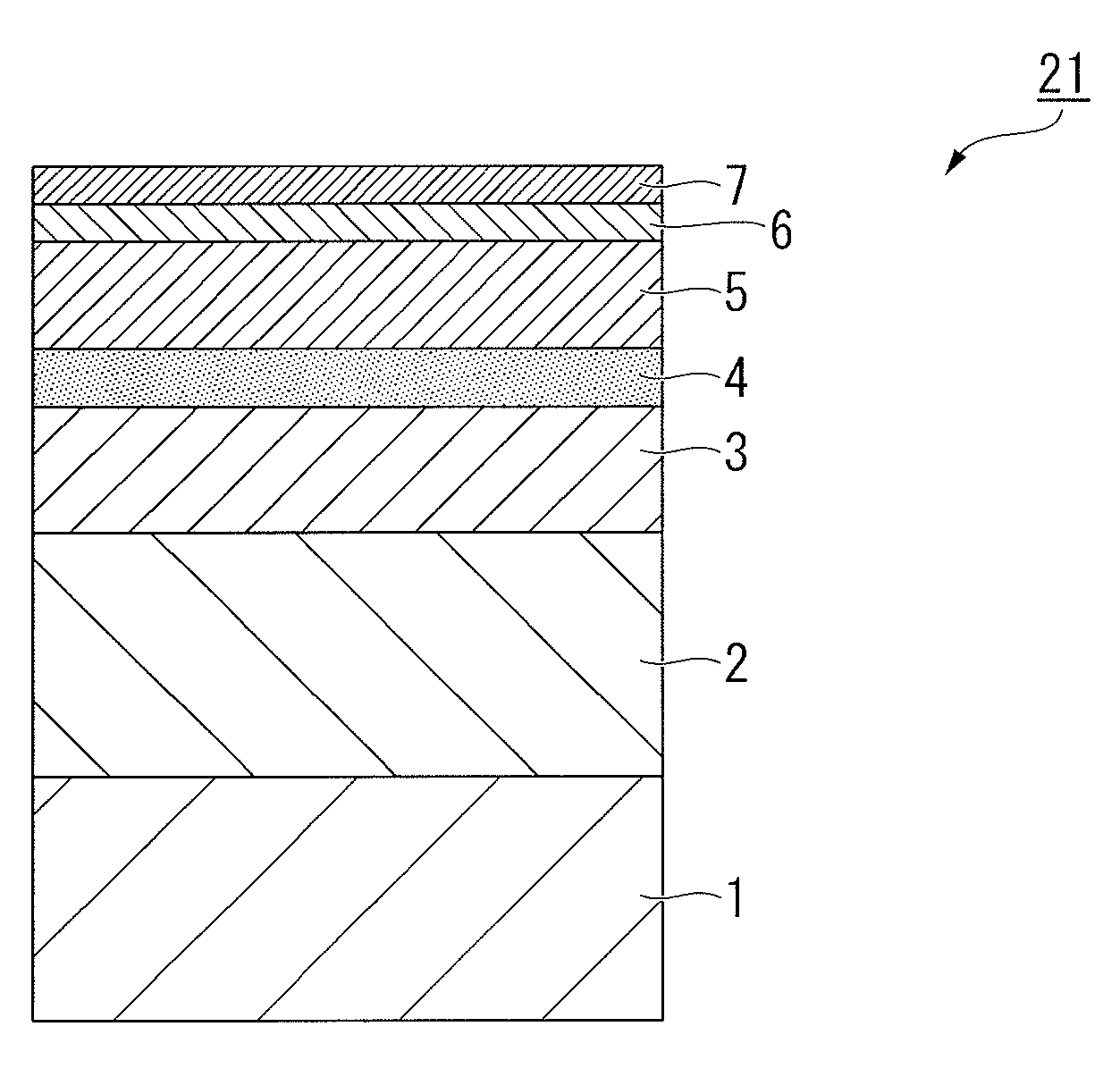
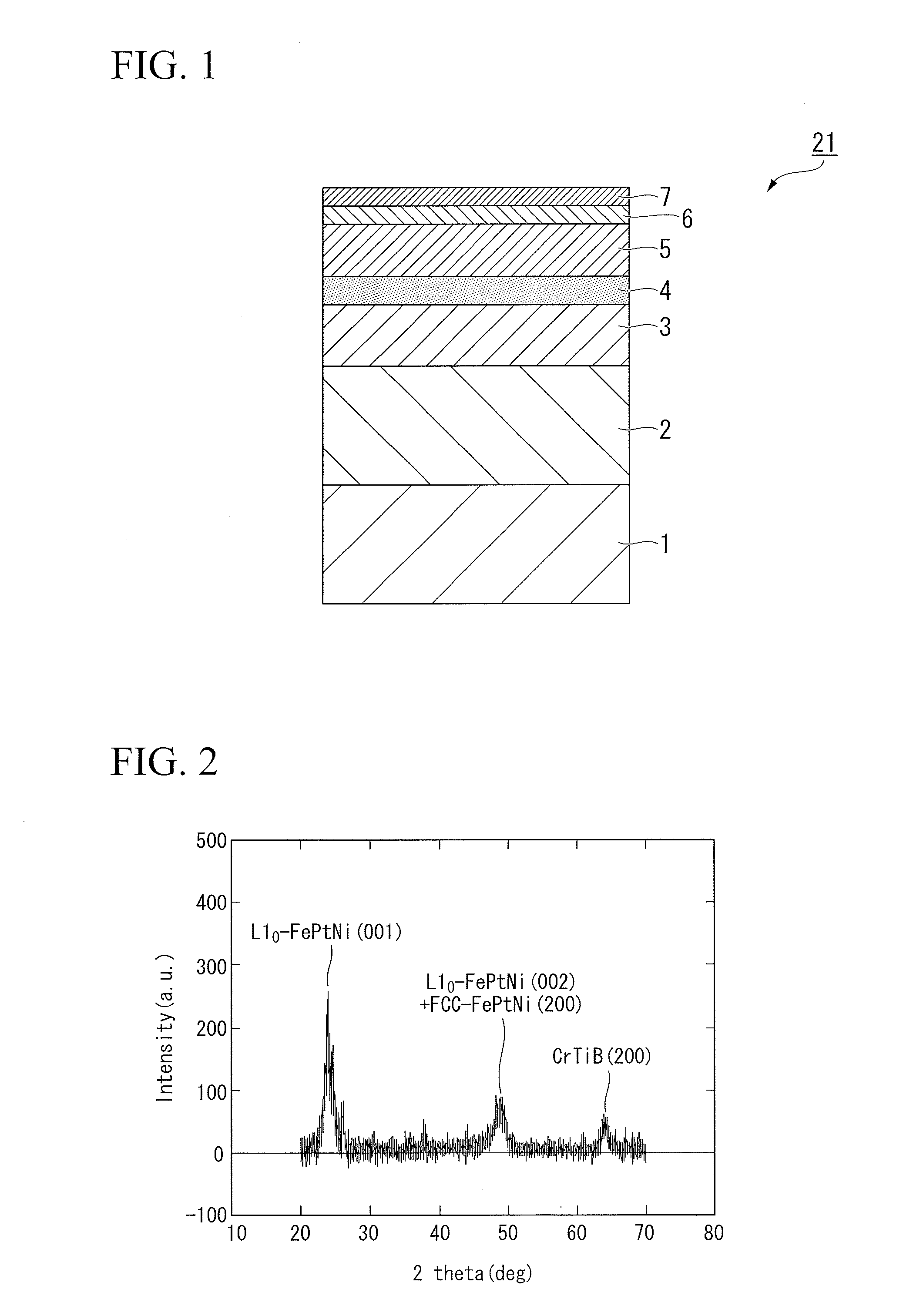
[0051]FIG. 1 illustrates one example of the layer structure of a magnetic recording medium prepared in these examples of the present invention.

[0052]A 100 nm Cr-50 at % Ti underlayer (first underlayer) 2 was formed on a glass substrate (the substrate) 1, and following heating to 380° C. using a lamp heater, a Cr alloy underlayer (second underlayer) 3 of 12 nm was formed. Subsequently, a 2 nm MgO underlayer (third underlayer) 4, a 12 nm 92 mol % (Fe-50 at % Pt-15 at % Ni)-8 mol % (SiO2) magnetic layer 5, and a 3 nm carbon protective film 6 were formed in a continuous manner within a vacuum deposition apparatus. Following removal from the vacuum apparatus, a lubricant film 7 of 1.7 nm was applied to each magnetic recording medium prior to evaluation of the recording and reproduction characteristics.

[0053]In the above production process, by altering the material used for the Cr alloy underlayer (second underlayer) 3 as shown in Table 1, magnetic recording med...

examples 2-1 to 2-16

, and Comparative Example 2

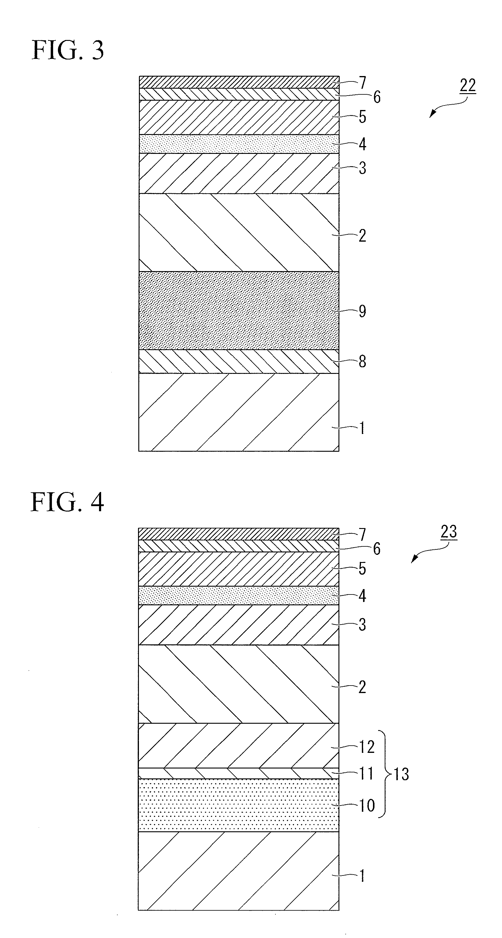
[0066]FIG. 3 illustrates one example of the layer structure of a magnetic recording medium prepared in these examples of the present invention.

[0067]A 10 nm MgO underlayer 8 and a 200 nm Ag heat sink layer 9 were formed on a glass substrate (the substrate) 1, and a seed layer (first underlayer) 2 of 20 nm was then formed. Subsequently, the substrate 1 was heated to 420° C., and an 8 nm Cr-20 at % Mo-10 at % B underlayer (second underlayer) 3, a 5 nm MgO underlayer (third underlayer) 4, a 10 nm 90 mol % (Fe-45at % Pt)-10 mol % (TiO2) magnetic layer 5, and a carbon protective film 6 were formed. A lubricant film 7 of 1.7 nm was applied to each magnetic recording medium prior to evaluation of the recording and reproduction characteristics.

[0068]In the above production process, by altering the material used for the seed layer (first underlayer) 2 as shown in Table 2, magnetic recording media of Examples 2-1 to 2-16 were produced.

[0069]Further, a magnetic recor...

examples 3-1 to 3-12

, and Comparative Example 3

[0078]FIG. 4 illustrates one example of the layer structure of a magnetic recording medium prepared in these examples of the present invention.

[0079]A soft magnetic underlayer (SUL) 13 having a total thickness of 50 nm and composed of a Ru layer 11 sandwiched between two layers 10 and 12 of an Fe-30 at % Co-3 at % Ta-1 at % Si-1 at % B alloy was formed on top of an amorphous substrate (the substrate) 1. Subsequently, a 20 nm amorphous seed layer (first underlayer) 2 was formed, and following heating of the substrate to 350° C., a 10 nm Cr alloy underlayer (second underlayer) 3 was formed. Following formation of the Cr alloy underlayer 3, a 5 nm MgO underlayer (third underlayer) 4 and a 6 nm Fe-30 at % Pt-10 at % Ni-30 at % C magnetic layer 5 were formed. Following formation of the magnetic layer 5, a 3 nm carbon protective film 6 was formed, and a lubricant film 7 was applied.

[0080]In the above production process, by altering the materials used for the see...


PUM


Abstract

A heat-assisted magnetic recording medium that includes a substrate 1, underlayers formed on the substrate 1, and a magnetic layer 5 which is formed on the underlayers and contains either an FePt alloy having an L10 structure or a CoPt alloy having an L10 structure as a main component, wherein the underlayers include a first underlayer 2 formed from an amorphous alloy, a second underlayer 3 formed from an alloy having a BCC structure containing Cr as a main component and also containing at least one element selected from among Ti, Mo, W, V, Mn and Ru, and a third underlayer 4 formed from MgO. Also, a magnetic storage device that uses the heat-assisted magnetic recording medium.

Description

TECHNICAL FIELD[0001]The present invention relates to a heat-assisted magnetic recording medium and a magnetic storage device using the same. Priority is claimed on Japanese Patent Application No. 2009-191167, filed Aug. 20, 2009, the content of which is incorporated herein by reference.BACKGROUND ART[0002]With the rapid ongoing development of the information society, there is considerable demand for further increases in the capacities of hard disk devices (HDD). In order to increase the surface recording density of a magnetic recording medium used in an HDD, the grain size of the magnetic crystal grains must be reduced. However, a problem arises in that as the magnetic grains are reduced in size, the thermal stability of the grains tends to deteriorate.[0003]The expression KuV / kT (wherein Ku represents the crystal magnetic anisotropy constant, V represents the magnetic grain volume, k represents Boltzmann's constant, and T represents the absolute temperature) is generally used as a...

Claims


Application Information

Patent Timeline
IPC IPC(8): G11B5/66G11B13/04
CPCG11B5/6088G11B5/656G11B2005/0021G11B5/82G11B5/7325G11B5/737
Inventor KANBE, TETSUYASASAKI, YUZOHASHIMOTO, ATSUSHI
Owner RESONAC CORP
Why Eureka
Try Eureka