Radiographic apparatus and radiographic system
a radiographic system and radiographic apparatus technology, applied in the direction of material analysis using wave/particle radiation, instruments, applications, etc., can solve the problems of reducing the absorption ability of x-rays, difficult to obtain shading differences, and inability to acquire image shading (contrast), so as to avoid configuring a vibration system, quick attenuation of driving targets, and rapid convergence of driving targets
- Summary
- Abstract
- Description
- Claims
- Application Information
AI Technical Summary
Benefits of technology
Problems solved by technology
Method used
Image
Examples
first modified embodiment
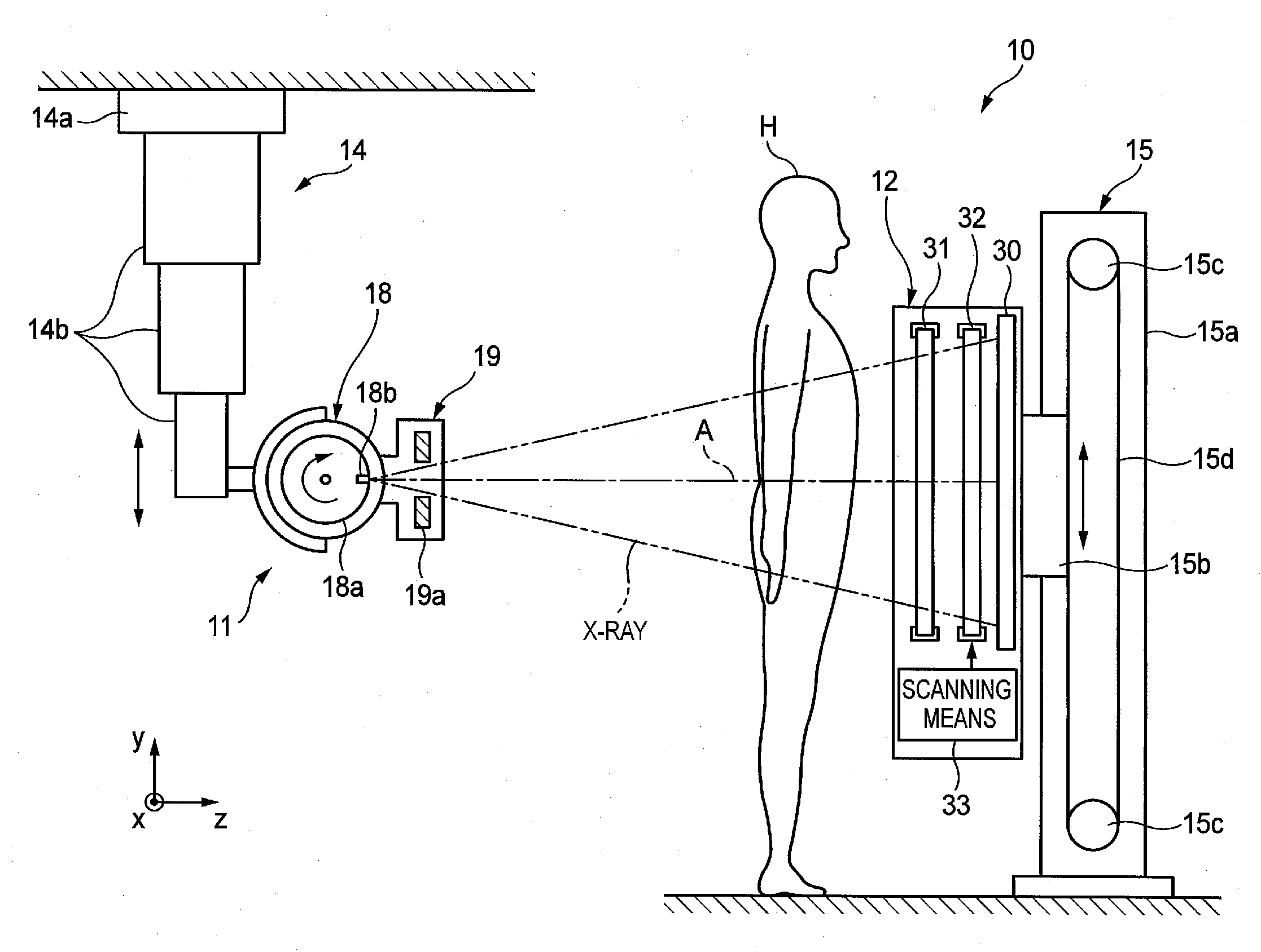
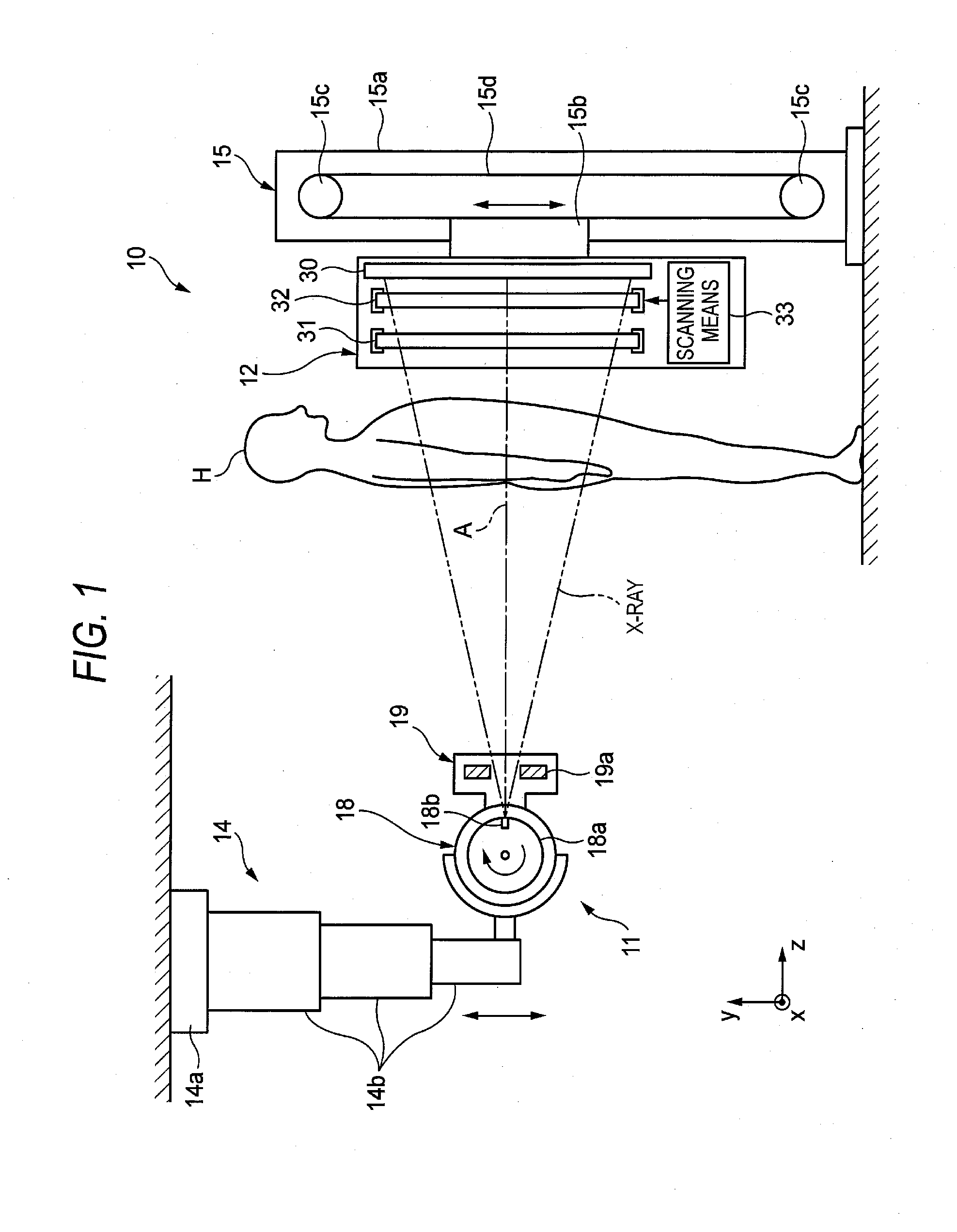
[0136]FIG. 11 shows a plurality of types of elastic members according to a The elastic members include a first coil spring 136 that is mounted on the central line CL passing to the operating point A of the piezoelectric actuator 35 and a second coil spring 137 that has a diameter smaller than that of the first coil spring 136 and is mounted at an inner side of the first coil spring 136. The respective natural frequencies of the first and second coil springs 136, 137 are different from each other and do not have a relation of an integer multiple. The first and second coil springs 136, 137 are coaxially mounted and the spring forces are balanced at both sides of the central line CL. Accordingly, it is possible to stably operate the second grating 32 without the inclination of the second grating 32.
second modified embodiment
[0137]FIG. 12 shows a plurality of types of elastic members according to a The elastic members include two coil springs 36, 37 having different natural frequencies. The spring forces of the coil springs 36, 37 are different. However, the coil springs 36, 37 are symmetrically arranged about the central line CL, so that the spring forces are balanced at both sides of the central line CL. Accordingly, the inclination of the second spring 32 is suppressed.
[0138]In FIG. 12, the coil springs 36, 37 are symmetrically arranged, when seen from a plan view of the second grating 32. However, the coil springs 36, 37 may be symmetrically arranged at both sides of a central line in a thickness direction of the second grating 32 (which central line is a line extending in the driving direction when the second grating 32 is bisected in a thickness direction). In this case, the inclination of the second grating 32 in the thickness direction is suppressed.
third modified embodiment
[0139]FIG. 13 shows a plurality of types of elastic members according to a The elastic members include two coil springs 36, 36 having the same frequency and one coil spring 37 having a natural frequency different from that of the coil springs 36. The two coil springs 36 are symmetrically arranged at both sides of the central line CL and one coil spring 37 is arranged on the central line CL, so that the coil springs 36, 37 are symmetrically arranged for each type of the natural frequencies. By doing so, since the spring forces are balanced at both sides of the central line CL, it is possible to prevent the second grating 32 from being inclined.
PUM
| Property | Measurement | Unit |
|---|---|---|
| displacement resolution | aaaaa | aaaaa |
| peak wavelength | aaaaa | aaaaa |
| tube voltage | aaaaa | aaaaa |
Abstract
Description
Claims
Application Information
 - R&D
- Intellectual Property
- Life Sciences
- Materials
- Tech Scout
- Unparalleled Data Quality
- Higher Quality Content
- 60% Fewer Hallucinations
Browse by: Latest US Patents, China's latest patents, Technical Efficacy Thesaurus, Application Domain, Technology Topic, Popular Technical Reports.
© 2025 PatSnap. All rights reserved.Legal|Privacy policy|Modern Slavery Act Transparency Statement|Sitemap|About US| Contact US: help@patsnap.com


