

Method and device for adjusting timing advance in uplink multiple points reception
- Summary
- Abstract
- Description
- Claims
- Application Information
AI Technical Summary
Benefits of technology
Problems solved by technology
Method used
Image

Examples
embodiment 1
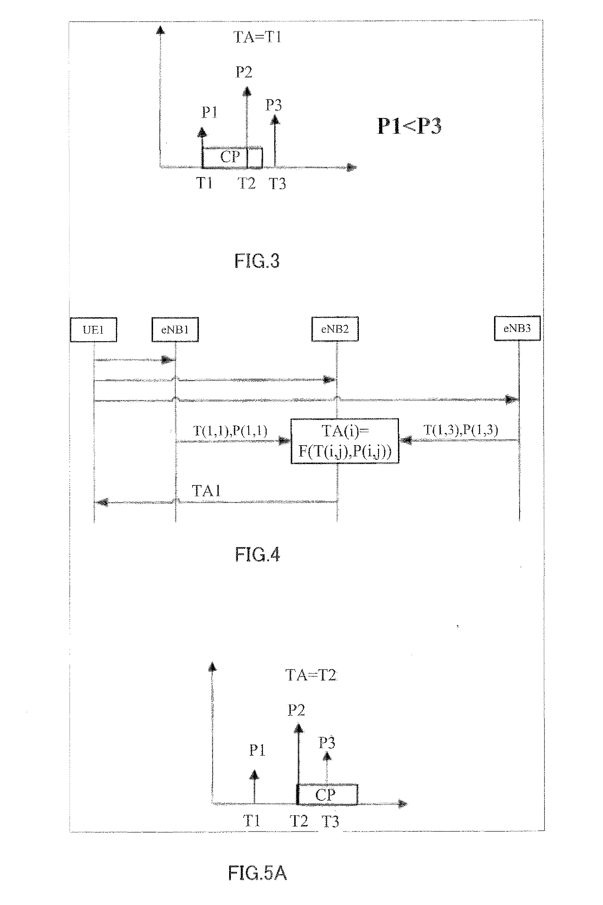
[0056]FIG. 4 is a diagrammatic representation of the signaling flow according to Embodiment 1 of the present invention.
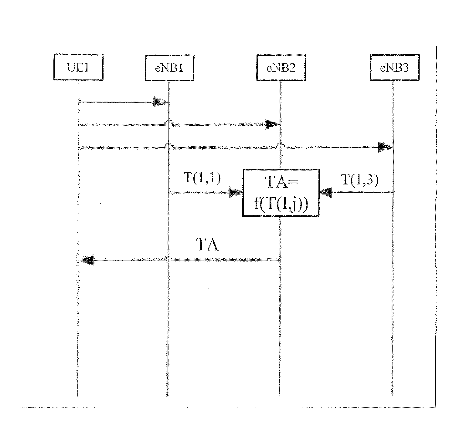
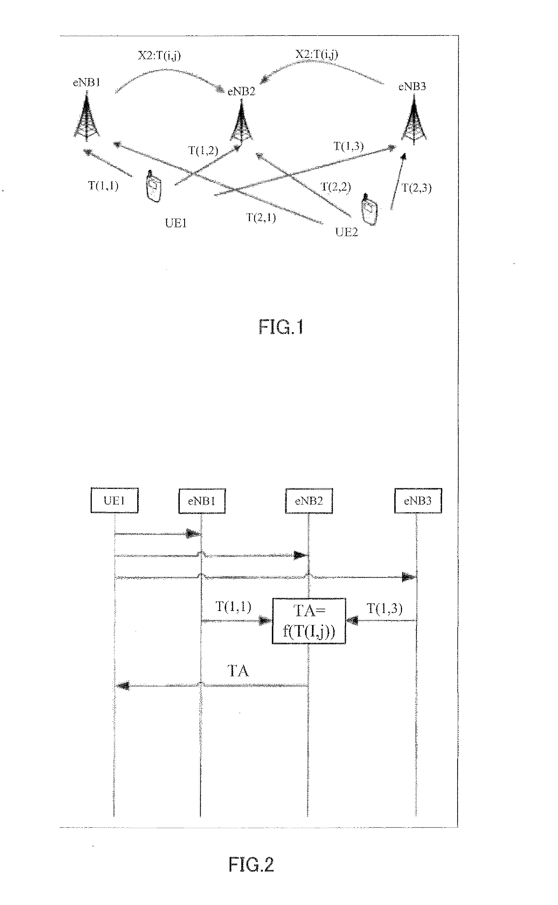
[0057]As shown in FIG. 4, in a method for adjusting an uplink time advancement amount in a communication system composed of a mobile terminal and a plurality of base stations according to Embodiment 1 of the present invention, first, base stations eNB 1, eNB 2, and eNB 3 measure respectively propagation delays T (1, 1), T (1, 2), and T (1, 3), and channel response powers P (1, 1), P (1, 2), and P (1, 3), from mobile terminal UE 1, after which measured propagation delays T (1, 1) and T (1, 3) and channel response powers P (1, 1), P (1, 2), and P (1, 3) are reported to serving station eNB 2 by non-serving stations eNB 1 and eNB 3, and then serving station eNB 2 measures an uplink time advancement amount of that mobile terminal based on received delay and power information, and propagation delay and power information measured by itself, after which serving station eNB ...
embodiment 2
[0068]In Embodiment 1, there may be a problem of signaling overhead when a non-serving station reports delay and power information to a serving station. First, in a method according to an embodiment of the present invention, it is necessary for irregular power information to be transmitted between base stations, and this increases signaling overhead, and since the time advancement amount is updated periodically, the increase in signaling overhead then increases the system load. In order to alleviate the above problem, the embodiment below is presented, in which signaling overhead caused by information transmission between base stations is reduced, and an advantageous effect of the present invention is achieved.
[0069]FIG. 7 is a diagrammatic representation of the signaling flow according to Embodiment 2 of the present invention.
[0070]As shown in FIG. 7, in a method of adjusting an uplink time advancement amount according to Embodiment 2 of the present invention, in step ST01 mobile t...
embodiment 3
[0077]FIG. 8 is a diagrammatic representation of the signaling flow according to Embodiment 3 of the present invention.
[0078]As shown in FIG. 8, in a method of adjusting an uplink time advancement amount according to Embodiment 3 of the present invention, in step ST01, if one predetermined condition (a threshold value determination condition “Is the threshold value exceeded?” is possible as in step ST04 in Embodiment 5 described later herein) is satisfied, transmission / reception section 604-2 of serving station eNB 2 reports all propagation delay and power information to non-serving stations eNB 1 and eNB 3. Here, transmission / reception section 604-2 of serving station eNB 2 reports stored propagation delay and power information measured beforehand by all related base stations to a non-serving station. That is to say, propagation delays T (1, 2) and T (1, 3) and channel response powers P (1, 2) and P (1, 3) are reported to non-serving station eNB 1, and propagation delays T (1, 1) a...
PUM
 Abstract
Description
Claims
Application Information