Method and Control Apparatus for Controlling a High-Pressure Fuel Supply Pump Configured to Supply Pressurized Fuel to an Internal Combustion Engine

a high-pressure fuel supply and control apparatus technology, which is applied in the direction of fuel injection apparatus, electric control, charge feed systems, etc., can solve the problems of affecting dominating the overall noise of the engine, and generating impact noise, so as to reduce noise and efficiently control

Active Publication Date: 2012-05-17
HITACHI LTD
View PDF5 Cites 27 Cited by
  • Summary
  • Abstract
  • Description
  • Claims
  • Application Information

AI Technical Summary

Benefits of technology

[0015]In view of the above-mentioned problems of the prior art, it is an object of the present invention to provide a method and a control apparatus for efficiently controlling a high-pressure fuel supply pump compris...

Problems solved by technology

When the normally-open intake valve reaches a fully open position of the intake valve, an impact noise is generated which, especially for lower engine speeds such as e.g. the idle condition, will even dominate the overall noise of the engine.
When the normally-open intake valve reaches a fully open position of the intake valve, an impact noise is generated which especially for lower engine speeds such as e.g. the idle condition will even dominate the overall noise of the engine.
However, the teaching of DE 10 2008 054 512 A1 and DE 101 48 218 A1 of applying another pulse of control current of the solenoid-actuated intake valve after shutting off the control current suffers from the problem that the timing and the control current value of the pulse for reducing the speed of the opening movement has to be very accurately adjusted in order to actually help to reduce the noise of the operation of the high-pressure fuel supply pump.
Specifically, if the timing of the pulse is too late or the control current value is too low, the pulse will be too late or too weak to reduce th...

Method used


Image

  • Method and Control Apparatus for Controlling a High-Pressure Fuel Supply Pump Configured to Supply Pressurized Fuel to an Internal Combustion Engine
  • Method and Control Apparatus for Controlling a High-Pressure Fuel Supply Pump Configured to Supply Pressurized Fuel to an Internal Combustion Engine
  • Method and Control Apparatus for Controlling a High-Pressure Fuel Supply Pump Configured to Supply Pressurized Fuel to an Internal Combustion Engine

Examples


first embodiment

[0069]FIG. 6 exemplarily illustrates the control of a solenoid-actuated intake valve according to the present invention. The upper row in FIG. 6 illustrates the plunger movement of the movable plunger 130 reciprocating between the bottom dead center position BDC and the top dead center position TDC. The middle row in FIG. 6 illustrates the control current applied to the solenoid coil 125 and the lower row in FIG. 6 illustrates the movement of the intake valve 120, in particular the valve member 121, between the fully open position and the fully closed position.

[0070]The basic control, principle in FIG. 6 is similar to the control principle described with reference to FIG. 4, however, in accordance with the first embodiment of the present invention, after the movable plunger 130 has reached the top dead center position TDC and is moving again towards the bottom dead center position. EDC, control current is applied again to the solenoid 125 during a second time period ΔT2. During a th...

second embodiment

[0071]FIG. 7 exemplarily illustrates the control of a solenoid-actuated intake valve according to the present invention. The upper row in FIG. 7 illustrates the plunger movement of the movable plunger 130 reciprocating between the bottom dead center position BDC and the top dead center position TDC. The middle row in FIG. 7 illustrates the control current applied to the solenoid coil 125 and the lower row in FIG. 7 illustrates the movement of the intake valve 120, in particular the valve member 121, between the fully open position and the fully closed position.

[0072]The basic control principle in FIG. 7 is similar to the control principle described with reference to FIG. 4, however, in accordance with the second embodiment of the present invention, after the movable plunger 130 has reached the top dead center position TDC and is moving again towards the bottom dead center position BDC, control current is applied again to the solenoid 125 during a second time period ΔT2. Specifically...

third embodiment

[0073]FIG. 8 exemplarily illustrates the control of a solenoid-actuated intake valve according to the present invention. The upper row in FIG. 8 illustrates the plunger movement of the movable plunger 130 reciprocating between the bottom dead center position BDC and the top dead center position TDC. The middle row in FIG. 8 illustrates the control current applied to the solenoid coil 125 and the lower row in FIG. 2 illustrates the movement of the intake valve 120, in particular the valve member 121, between the fully open position and the fully closed position.

[0074]The basic control principle in FIG. 8 is similar to the control principle described with reference to FIG. 4, however, in accordance with the third embodiment of the present invention, after the movable plunger 130 has reached the top dead center position TDC and is moving again towards the bottom dead center position BDC, control current is applied again to the solenoid 125 during a second time period ΔT2. Specifically,...


PUM


Abstract

The present invention relates to a method and an apparatus for controlling a high-pressure fuel supply pump configured to supply pressurized fuel to an internal combustion engine, with a solenoid-actuated intake valve being configured to be biased into a first direction towards a first stop position of the intake valve by means of a biasing force and being configured to be displaced against the biasing force into a second direction opposite to the first direction towards a second stop position of the intake valve by means of magnetic force and to be kept at the second stop position by means of magnetic force. The method includes applying control current to the solenoid-actuated intake valve for displacing the intake valve into the second direction to the second stop position and for keeping the intake valve at the second stop position during a first time period by means of magnetic force.

Description

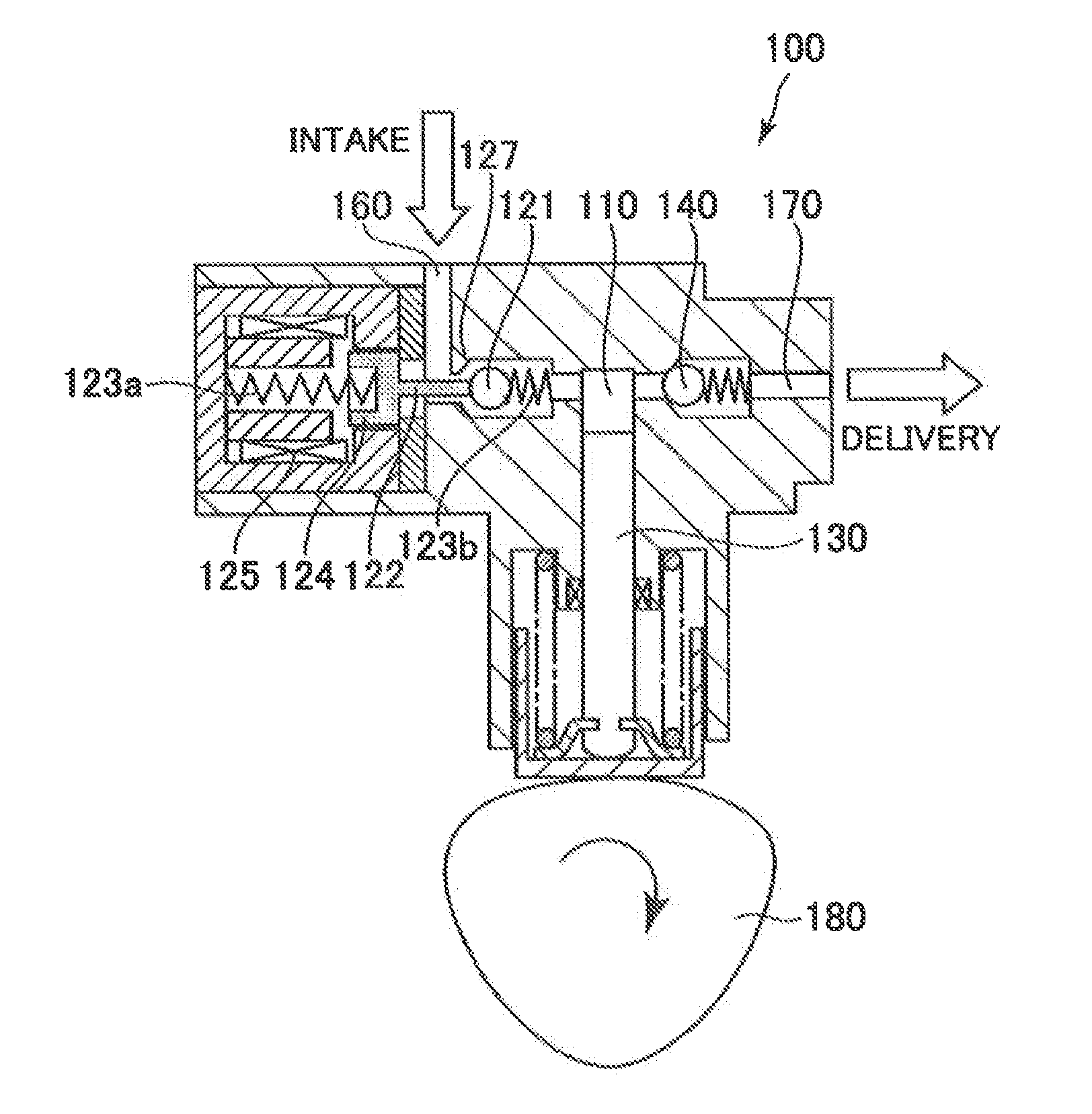
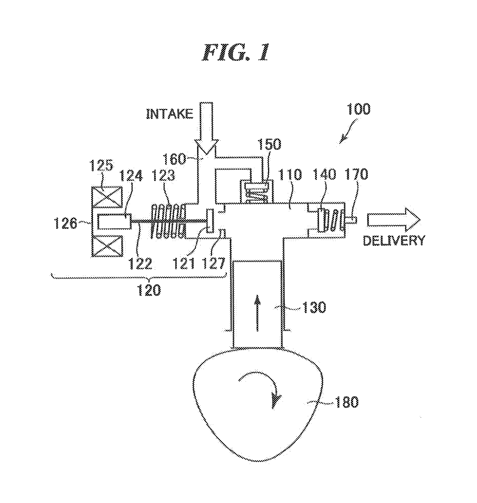
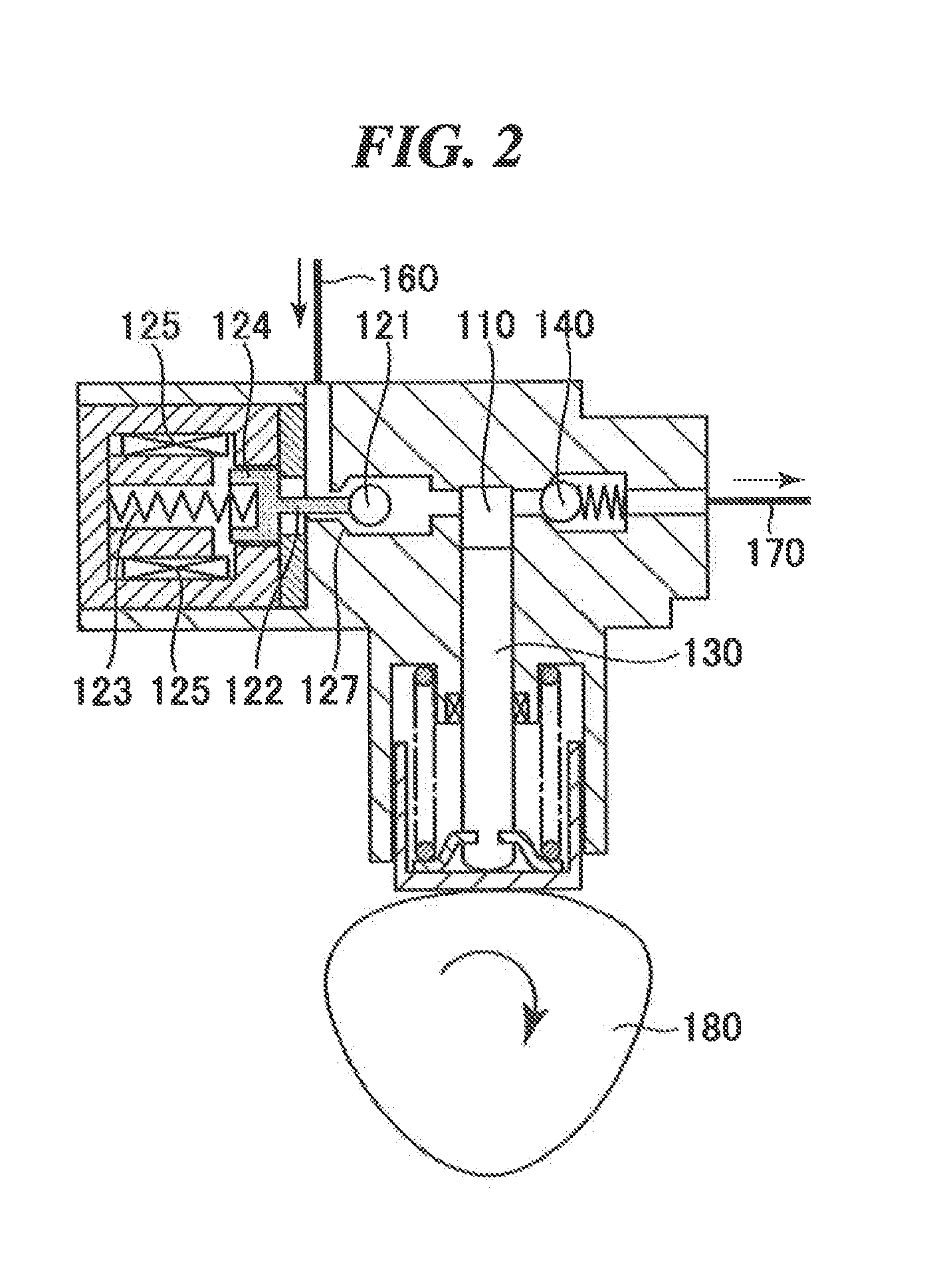
BACKGROUND OF THE INVENTION[0001]1. Field of the Invention[0002]The present invention relates to a method and a control apparatus for controlling a high-pressure fuel supply pump which is configured to supply pressurized fuel to an internal combustion engine, in particular to a common rail having a plurality of fuel injectors for injecting pressurized fuel into a combustion chamber of the internal combustion engine. Specifically, the present invention relates to a method and a control apparatus for controlling a high-pressure fuel supply pump which comprises a compression chamber, a normally-open-type solenoid-actuated intake valve for delivering unpressurized fuel to the compression chamber, a movable plunger reciprocating in the compression chamber between a first plunger position, e.g. the so-called bottom dead center position, and a second plunger position, e.g. the so-called top dead center position, for pressurizing fuel in the compression chamber, and a discharge valve for di...

Claims


Application Information

Patent Timeline
IPC IPC(8): F02M37/04
CPCF02D41/20F02D41/3845F02M63/0225F02D2041/2037F02M59/466F02D2041/2027
Inventor BORG, JONATHANWATANABE, MASANORIDETTMERING, ULFTOKUO, KENICHIRO
Owner HITACHI LTD
Why Eureka
Try Eureka