
Apparatus and Method for Small Scale Wind Mapping

Inactive Publication Date: 2012-05-17
UTAH STATE UNIVERSITY
View PDF10 Cites 15 Cited by
  • Summary
  • Abstract
  • Description
  • Claims
  • Application Information

AI Technical Summary

Benefits of technology

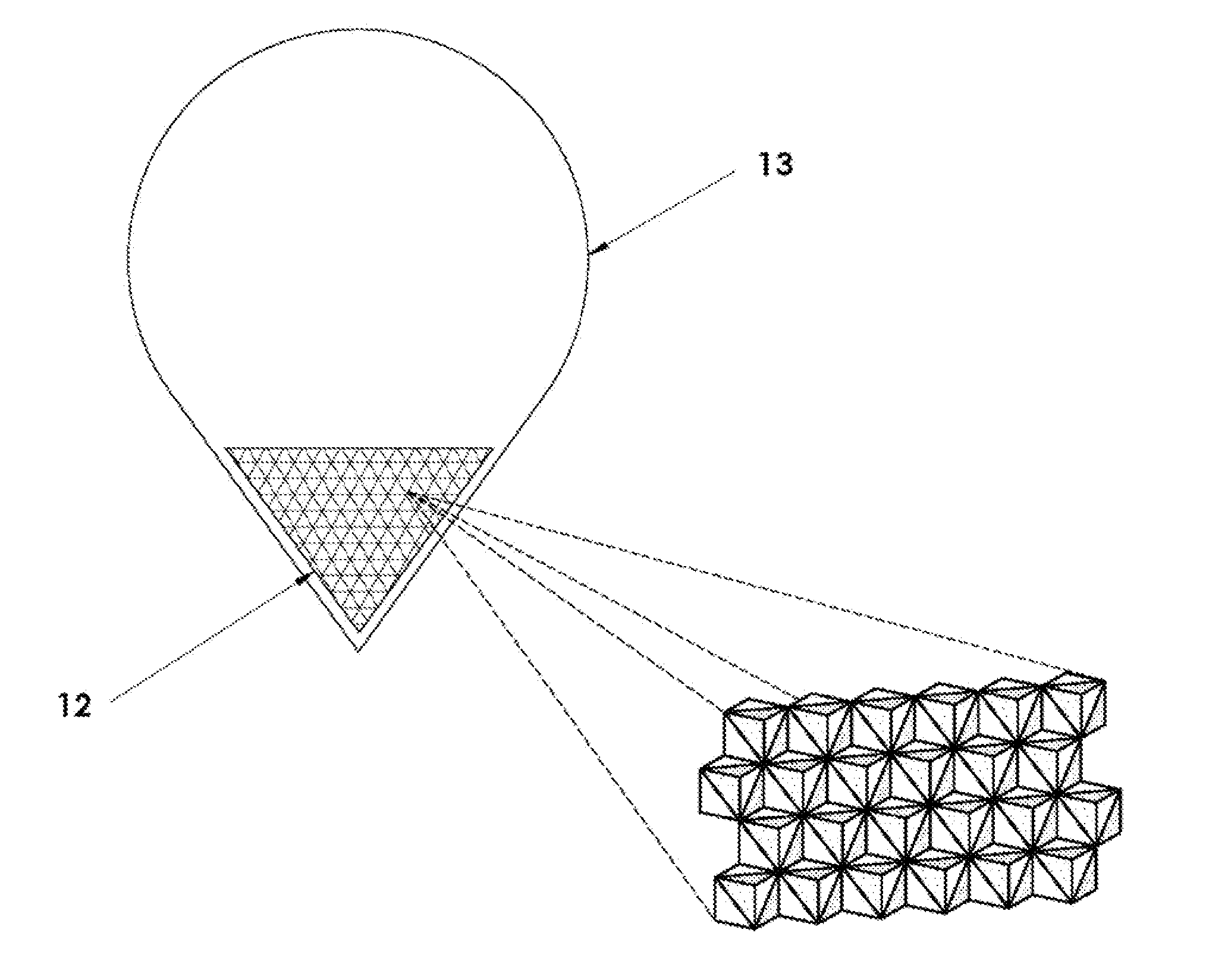
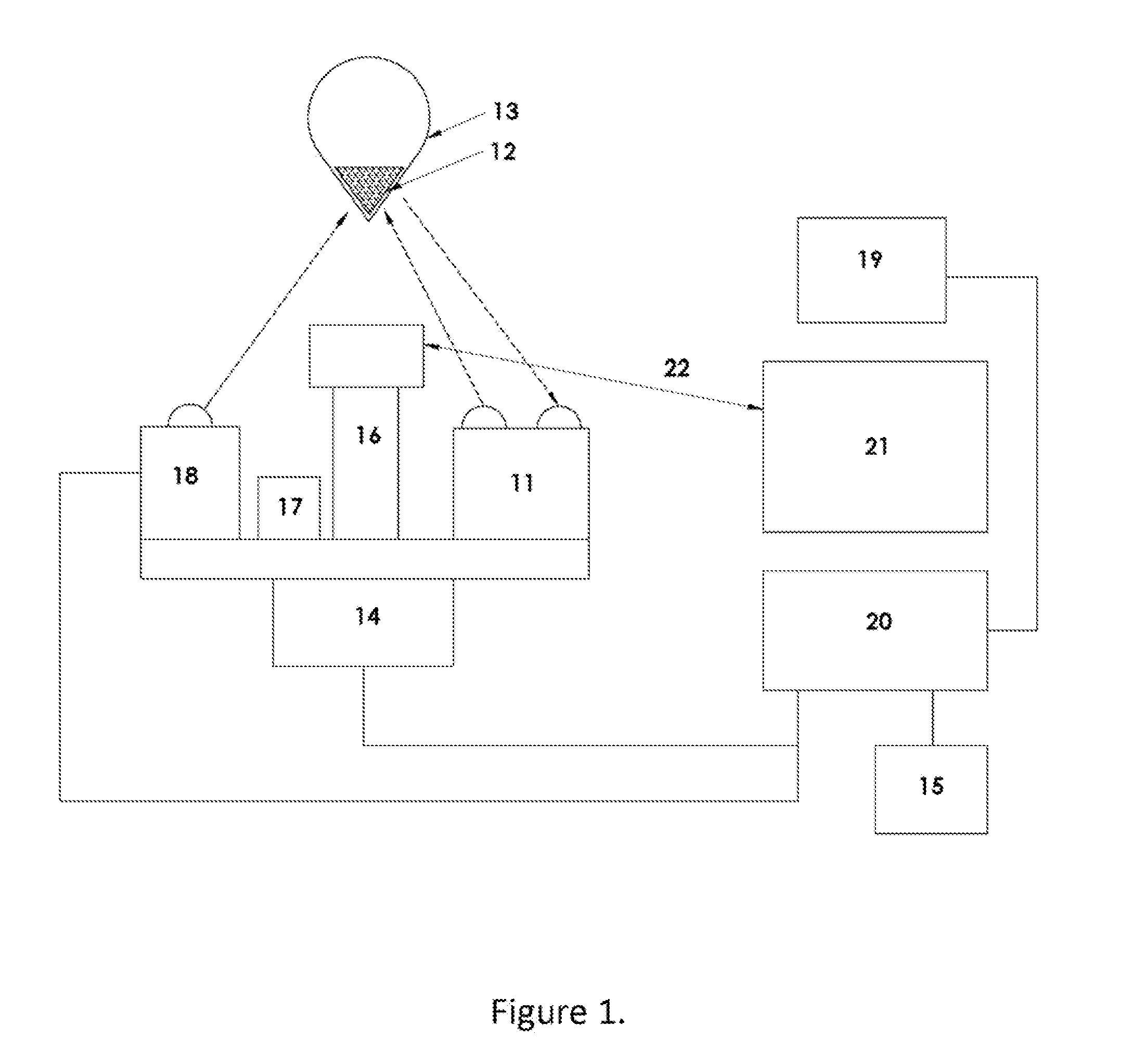
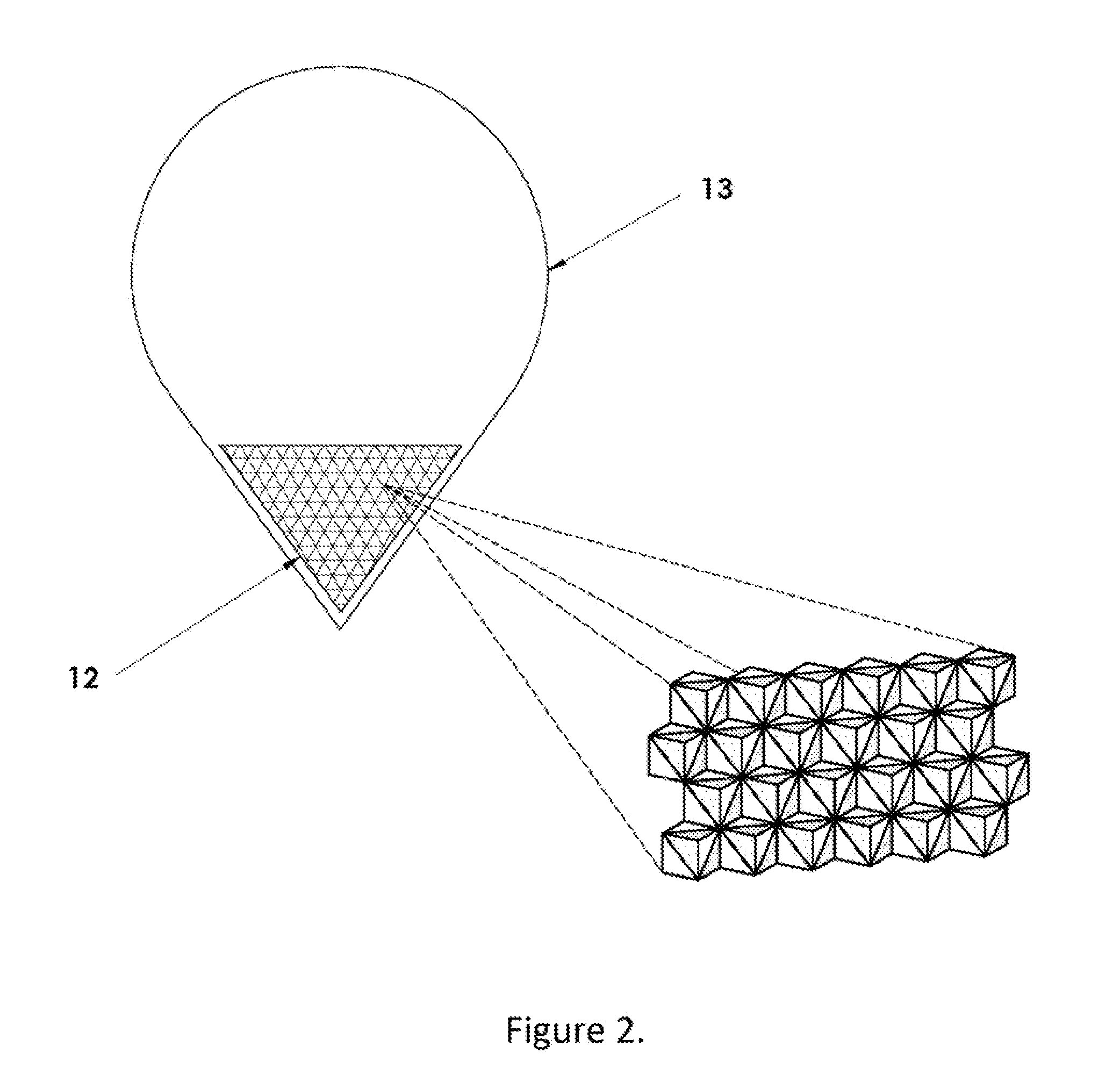
[0013]Optical enhancement of the sensor is accomplished two ways: the preferred embodiment consists of lightweight retroreflectors attached to the balloon to enhance the reflection of the laser pulse back to the rangefinder; the maximum detectable range to the balloon is always enhanced by this method. A second enhancement necessary for nighttime operation is a high intensity light that illuminates the balloon retroeflectors from the ground collinearly with the laser and thereby enhances the balloon's trackability with the automatic tracker. A third enhancement method is the addition of small lights to the balloon payload itself, within the limitations set by lift requirements and intensity requirements of the automatic tracker.
[0016]The disclosed wind mapping apparatus and method is inexpensive in both equipment and operation. The apparatus is easily deployable, can provide real time data, is accurate, precise, and portable. The method can be used for the calibration and validation of other remote sensors, and has widespread applicability for prospecting for favorable wind energy sites, identifying optimal locations for wind turbines, and evaluating wind characteristics to support civil and environmental engineering studies.

Problems solved by technology

A major drawback of anemometers is that they provide only point measurements of wind speed at the fixed location of the sensor.
Thus they cannot ordinarily provide either detailed wind profiles very far above ground or the characterization of wind patterns over an extended site.
An obvious counter argument to this is the use of very tall, fixed towers to operate anemometers at the typical heights of wind turbines; indeed, long term data from such towers is often required for selecting suitable turbine sites.
However, the very cost of installing of such tower is often prohibitive in the face of uncertain wind projections and the risk of failure due to uninformed tower placement.
The principle drawbacks to Soder and wind Lidar are the relatively high cost, complexity, and the mean time between failures of the systems and the difficulty of installing or relocating them.
Both Soder and Lidar have limitations with regard to true 3D wind characterization.
In addition, Soder systems primarily provide measurements of mean wind, and parameters such as wind speed standard deviation, wind direction standard deviation, and wind gust, are usually either not available or not reliable with sodars.
Firstly, the radiosonde balloons are expensive; consequently they are restricted to applications such as weather monitoring where infrequent wind profiles are acceptable.
Secondly, because of factors (such as size) to be explained herein, the balloons are susceptible to lift instabilities that degrade the wind measurement accuracy.
Other difficulties with the above sensor systems are the relative awkwardness of theodolite measurements, the cost of accurate radar systems, and the material “footprint” of balloons and payloads sent into the environment without recovery.

Method used


Image

  • Apparatus and Method for Small Scale Wind Mapping
  • Apparatus and Method for Small Scale Wind Mapping
  • Apparatus and Method for Small Scale Wind Mapping

Examples


Embodiment Construction

[0023]In the following description, numerous specific details are provided for a thorough understanding of specific preferred embodiments. However, those skilled in the art will recognize that embodiments can be practiced without one or more of the specific details, or with other methods, components, materials, etc. In some cases, well-known structures, materials, or operations are not shown or described in detail in order to avoid obscuring aspects of the preferred embodiments. Furthermore, the described features, structures, or characteristics may be combined in any suitable manner in a variety of alternative embodiments. Thus, the following more detailed description of the embodiments of the present invention, as represented in the drawings, is not intended to limit the scope of the invention, but is merely representative of the various embodiments of the invention.

[0024]Wind field mapping refers to the process of measuring the localized wind at points in space and plotting the v...


PUM


Abstract

An apparatus and method for wind profiling using a lighter than air tracer balloon moving under the influence of air currents. A retroreflective target is attached to the tracer balloon to improve the intensity of a return signal reflected back to the rangefinder. After the balloon is released, the rangefinder and attitude sensor are used to measure the range and direction angles of the retroreflective target on the tracer balloon at periodic time intervals. The recorded trajectory data are processed by a computer program using data smoothing and filtering techniques to calculate the wind velocity components, horizontal wind speed and direction, and an estimate of wind shear,

Description

FIELD OF THE INVENTION[0001]This invention relates to a method for mapping wind profiles as functions of time and the geographical coordinates and in particular to a method for measuring the position of a lighter than air balloon under the influence of air currents.BACKGROUND OF THE INVENTION[0002]Wind profiling and wind measurement systems are important for a wide range of applications including wind farm prospecting and micrositing, calibration and validation of remote sensors, wind loading studies, air pollution studies, airborne recreations, airdrops of personnel and supplies, and predictions of the motion of hazardous releases. Wind profiling supports the development, installation, and operation of wind turbines by identifying favorable wind energy sites, characterizing dynamic changes and diurnal patterns in the wind field, optimizing wind turbine locations with respect to local wind conditions, and identifying interactions between turbines in an existing facility. Wind-field ...

Claims


Application Information

Patent Timeline
IPC IPC(8): G06K9/00H04N7/18B64B1/40G01C3/08G01W1/00
CPCG01W1/08
Inventor WILKERSON, THOMASMARCHANT, ALAN B.BRADFORD, WILLIAM JAMESWOJCIK, MICHAEL
Owner UTAH STATE UNIVERSITY
Learn More