Frequency converter

a frequency converter and turbine technology, applied in the direction of dc-ac conversion without reversal, machine/engine, electric generator control, etc., can solve the problems of large installation cost and low output, inherently periodical or unpredictable, and structural challenges, and achieve the effect of low output and large installation cos

Active Publication Date: 2012-05-24
AKER SOLUTIONS AS
View PDF5 Cites 25 Cited by
  • Summary
  • Abstract
  • Description
  • Claims
  • Application Information

AI Technical Summary

Benefits of technology

[0013]It is an object of the present solution to provide a solution that can help satisfying mankind's ever increasing power consumption in an environmental friendly way. It is also an object for the present invention to provide a solution to the problems regarding the large installation costs and low output of today's wind turbines, and also regarding the structural challenges related to placing large and heavy components on the top of a tall structure and the limited amount of available space within a wind turbine nacelle.
[0042]In an alternative future embodiment of the invention the energy storage capacity within the dc-link(s) could be enhanced by energy dense batteries or super capacitors and enable better island-mode operation of a single or some wind turbines, in addition to higher tolerances versus transient power grid events.

Problems solved by technology

A common feature for these sources of energy is that they are inherently periodical or unpredictable, as tidal flows and perhaps solar radiation, costly in development and sometimes volatile.
It is, however, burdened with large installation costs and low output.
This leads to structural challenges related to placing large and heavy components on the top of a tall structure, experiencing formidable thrust from stiff winds.
Also, the amount of available space within a wind mill nacelle is limited.
Another challenge related to wind power is the unpredictability associated with wind speed.
If the torque from the blades becomes too large for the machine, the converter may increase the frequency and hence the rotor speed.

Method used


Image

  • Frequency converter
  • Frequency converter
  • Frequency converter

Examples


Embodiment Construction

[0069]The system is intended to be connected to a turbine, for example a wind turbine. A typical wind turbine is illustrated in FIG. 3 and comprises at least one turbine blade 1 connected to a rotating hub 2. The hub is connected to a turbine housing / nacelle 3 mounted atop a tower, and the nacelle 3 rotates to face the wind by means of controlled servo motors.

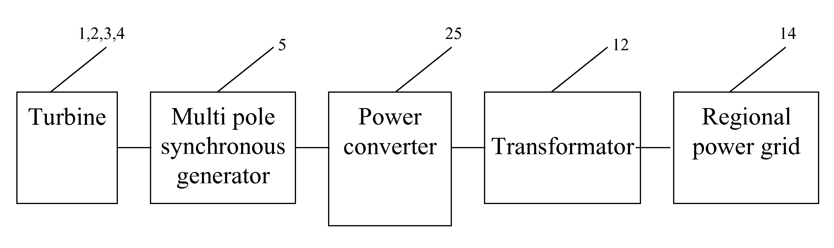
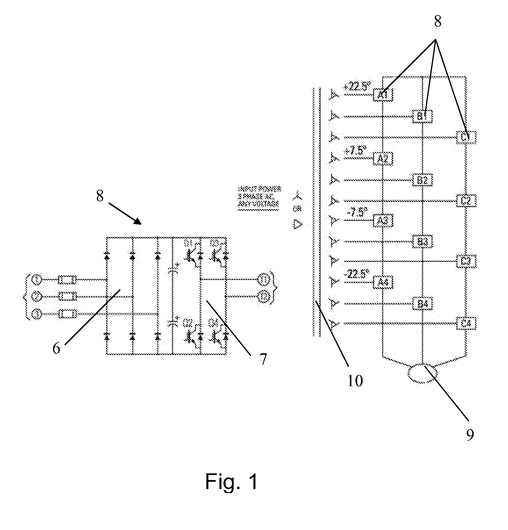
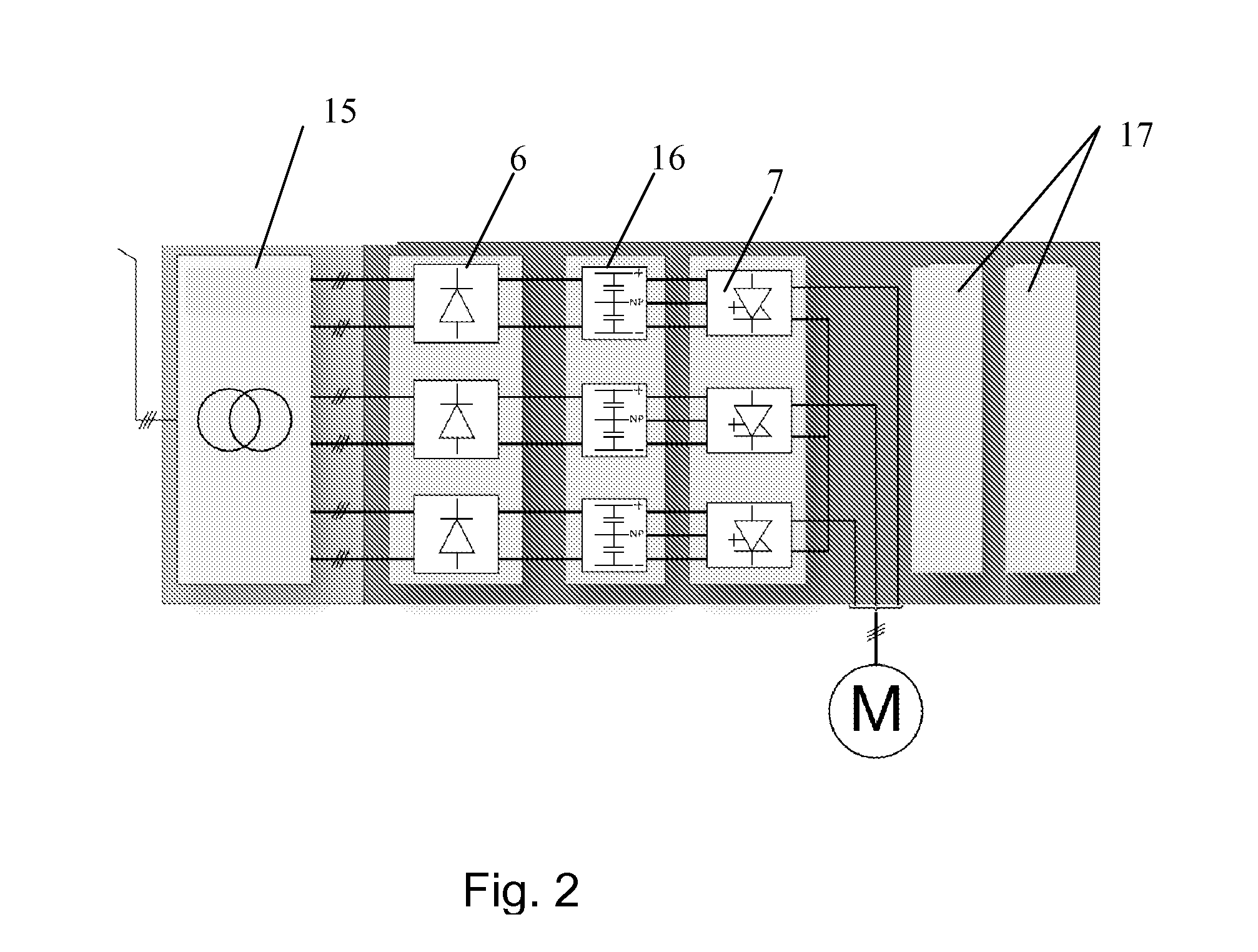
[0070]FIG. 4 shows a schematic view of the system according to the present invention. The FIG. 4 shows the main components of the system which comprises the turbine 1, 2, 3, 4 with the rotating hub 2 which drives a multi pole synchronous generator 5 situated in the nacelle 3. The generator 5 can have permanent magnets or rotor field windings. The multi pole generator 5 has galvanic isolated stator windings corresponding to the number of rotor poles and is therefore suited for a frequency converter interface of a type that can add up the voltages from different stator winding groups, which typically will be a multi level frequen...


PUM


Abstract

The inventions relates to a system for conditioning of power from a turbine, the turbine comprising at least one turbine blade (1) connected to a rotating hub (2), the rotating hub (2) is arranged to drive a generator (5). The generator is a multi pole synchronous generator (5) connected via a plurality of galvanic isolated three-phase cables (11) to a multi level frequency converter (25), the generator (5) also being arranged to feed current to the frequency converter (25) through the three-phase cables (11). The multi level frequency converter (25) is constituted by a plurality of elements arranged in columns and coupled in cascading order to add inverted voltage.

Description

FIELD OF THE INVENTION[0001]This invention relates generally to a frequency converter associated with a turbine. More particularly, this invention relates to the conditioning of power from a variable speed turbine, for example a wind turbine, connected to a separately excited- or permanent magnet synchronous machine.BACKGROUND OF THE INVENTION AND PRIOR ART[0002]As fossil energy sources reaches their peak production and their availability decline, need for renewable energy increases in pace with mankind's ever increasing consumption. Easily available sources of renewable energy have, to a large extent, already been developed as with fossil sources. This is true, especially for hydro power. In other words, the need is for new renewable energy sources, such as wind-, solar-, tidal- or wave power. A common feature for these sources of energy is that they are inherently periodical or unpredictable, as tidal flows and perhaps solar radiation, costly in development and sometimes volatile....

Claims


Application Information

Patent Timeline
Patent Type & Authority Applications(United States)
IPC IPC(8): H02M5/02H02J3/00
CPCF03D7/0224H02M5/458H02M7/483H02M7/49H02P2101/15H02P25/22Y02E10/723Y02E10/76H02P9/08F03D7/026F03D9/257F03D15/10Y02E10/72H02M7/4833
Inventor BJERKNES, OLE JOHAN
Owner AKER SOLUTIONS AS
Why Eureka
Try Eureka