Eureka AIR delivers breakthrough ideas for toughest innovation challenges, trusted by R&D personnel around the world.

Implement attachment having a hydraulically controlled locking function

a technology of hydraulic control and locking function, which is applied in the direction of fluid pressure sealing joints, couplings, basic electric elements, etc., can solve the problems of affecting the safety of drivers, so as to achieve the effect of reducing the risk of locking failur

Inactive Publication Date: 2012-05-24
OILQUICK
View PDF11 Cites 4 Cited by
  • Summary
  • Abstract
  • Description
  • Claims
  • Application Information

AI Technical Summary

Benefits of technology

[0015]Since the stroke length of the plunger means normally is directly proportional to the supplied volume of hydraulic medium to the actuator thereof, measuring of the volume gives an indication of how long the lock plunger means has been displaced. The volume that represents the stroke length that corresponds to correct clamping can easily be determined.
[0038]Two or more lock plungers entail great coupling safety, and a co-ordination in this way of locking movement and interconnection movement of the hydraulics gives a quick and safe connection. The measuring device according to the invention is particularly expedient to apply in such a design. However, it should be appreciated that the invention is applicable also to plungers arranged in other ways, e.g., counter-directed and that are disposed in the cross-direction in relation to the hydraulic interconnection direction.

Problems solved by technology

In the coupling-together disclosed in EP 602 165 and other similar systems, problems may arise as regards guaranteeing a correct coupling-together.
A specific problem with this kind of coupling-together of an implement with the implement attachment is the possibility of determining if the lock plunger or plungers becomes / become correctly positioned in relation to the other bracket pin, i.e., the element of the implement that co-operates with the lock plunger for the locking.
If the lock plunger, when it is to be activated for locking, is incorrectly directed, there is a risk of the locking not being accomplished.
However, normally this is a relatively small problem since it is easy for the driver of the working machine to observe this.
This is more difficult to detect for the driver since the lock plunger has not encountered any obstacle in the activation stroke and as the view normally is obscured to be able to see this with the eyes.
If the driver then, in belief that the implement is correctly attached, lifts the same, there is a risk of accidents when the implement come loose.

Method used


Image

  • Implement attachment having a hydraulically controlled locking function
  • Implement attachment having a hydraulically controlled locking function
  • Implement attachment having a hydraulically controlled locking function

Examples


embodiment examples

DESCRIPTION OF EMBODIMENT EXAMPLES OF THE INVENTION

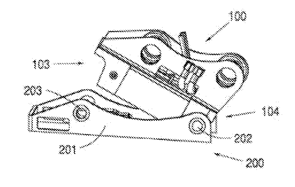
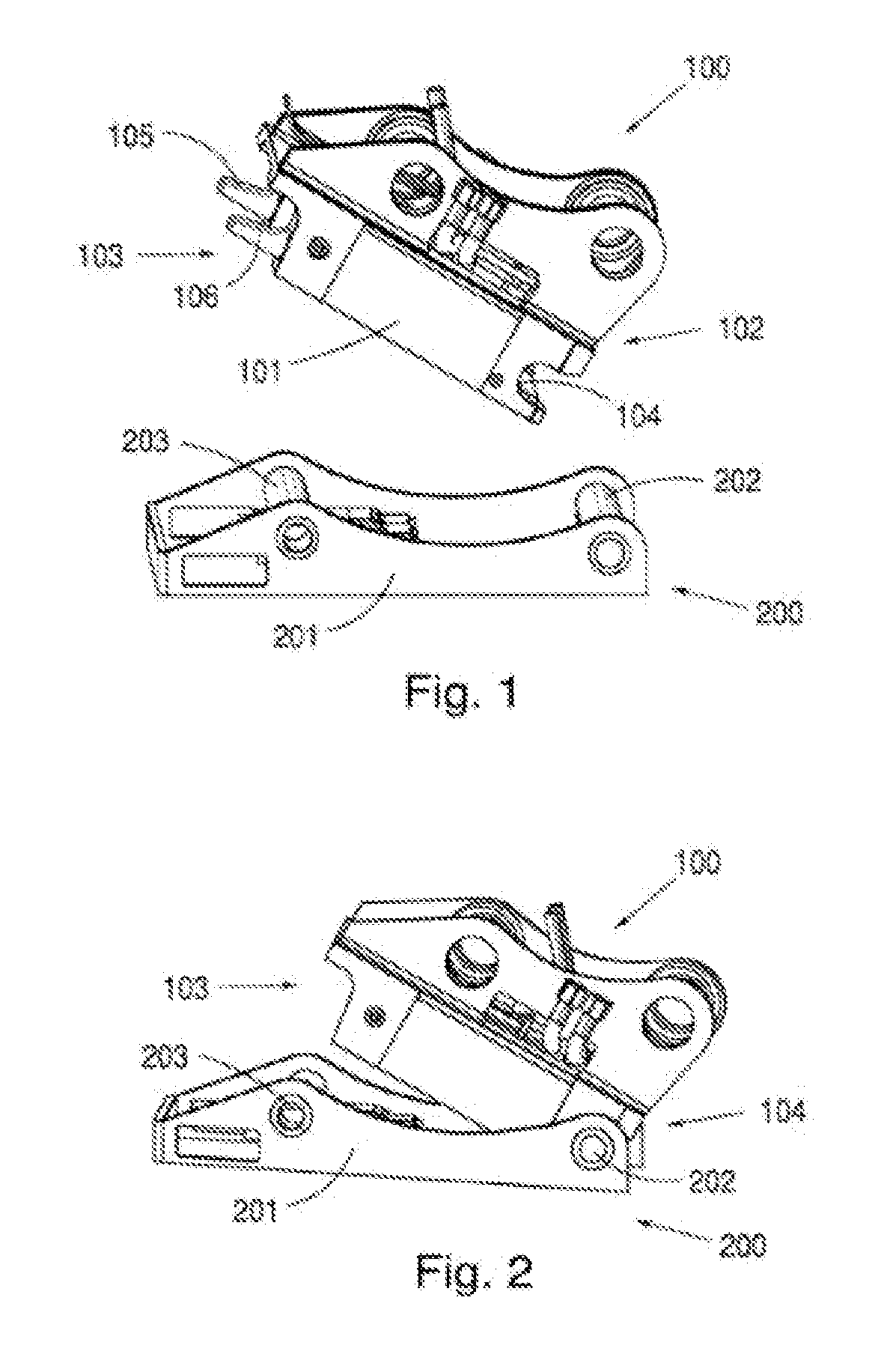
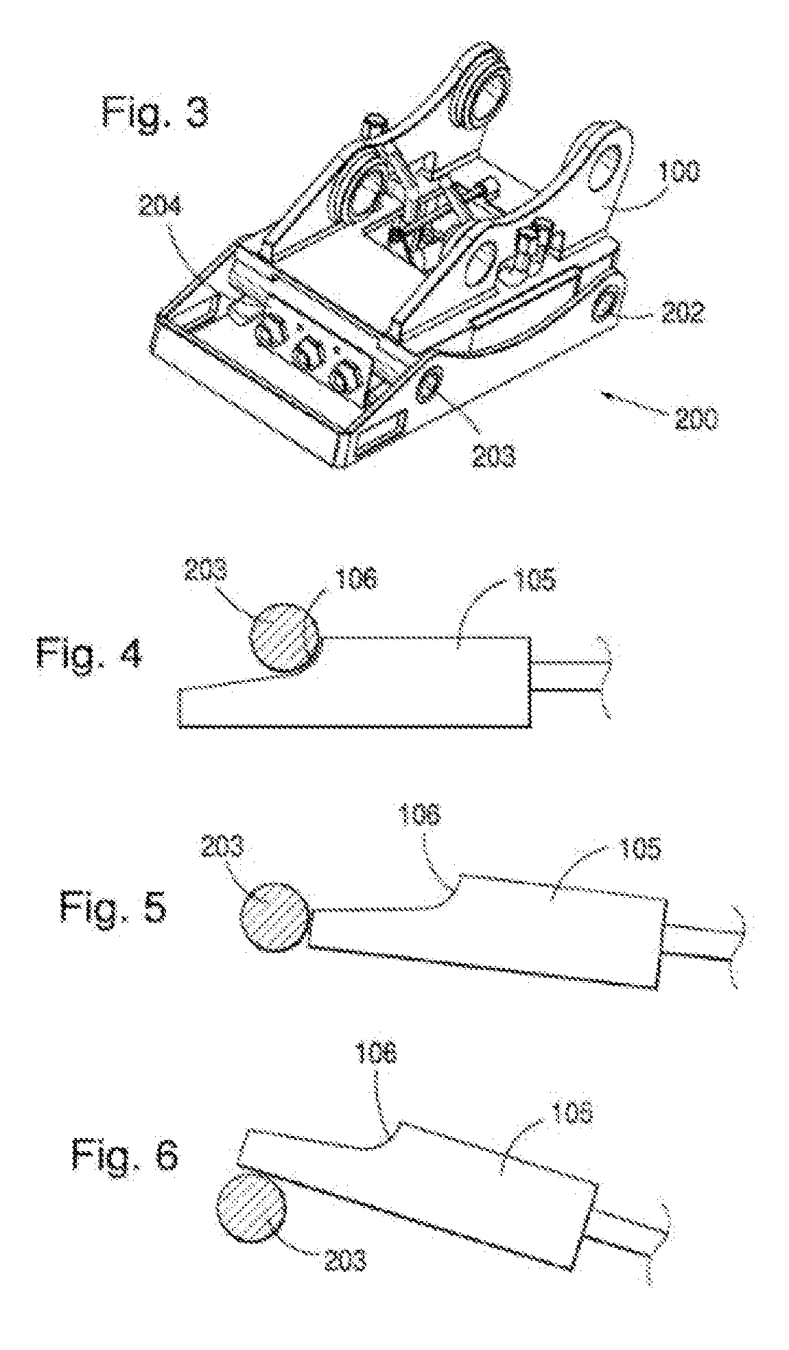
[0057]In FIGS. 1-3, a known system is described for the coupling-together of an implement attachment and a working implement. What is shown in these figures and the description in connection with the same is accordingly comprised in prior art, such as, for instance, is disclosed in EP 602 165 mentioned and that is hereby referred to.

[0058]The system in FIG. 1 consists accordingly of an implement attachment 100 and a working implement 200. The implement attachment 100 is intended to be mounted on a working machine, which however is not shown in the figure. The working implement 200 comprises an implement bracket 201 that is a part that is coupled together with the implement attachment 100 and is of a standardized design for different kinds of working implements. The active part of the working implement is not shown in the figure. This is formed differently for different purposes. By the system, accordingly working implements intended...


PUM


Abstract

An implement attachment for a working machine. The implement attachment comprises lock plungers having a hydraulic actuator. The lock plungers are arranged for locking co-operation with an implement. Hydraulic medium supply means is arranged for supply of hydraulic medium to the actuator. The hydraulic supply means is provided with a measuring device arranged to measure the volume of hydraulic medium that is supplied to the actuator. A working machine provided with the implement attachment and use of the implement attachment are included.

Description

FIELD OF THE INVENTION[0001]The present application relates to an implement attachment for a working machine, which implement attachment comprises a lock plunger means provided with a hydraulic actuator and arranged for locking co-operation with an implement, and hydraulic medium supply means for the supply of hydraulic medium to the actuator.[0002]The invention also concerns a working machine provided with an implement attachment according to the invention.[0003]In a second aspect of the invention, it relates to a use of the invented implement attachment.BACKGROUND OF THE INVENTION[0004]During the last decades, the use of implement attachment systems for quick replacements of buckets and implements in connection with working machines such as wheel-loaders, material handlers and other machine types has become a matter of course on most markets in Europe. Simultaneously, the development has gone quickly from simple mechanical solutions, wherein the driver leaves the driver's cab and ...

Claims


Application Information

Patent Timeline
IPC IPC(8): E02F9/00
CPCE02F3/3622E02F3/3627E02F3/3654Y10T403/22E02F9/2228F15B15/2838E02F3/3663E02F3/3609
Inventor SONERUD, ÅKE
Owner OILQUICK
Why Eureka
Eureka Blog
Learn More