Microtitration plate

a microtitration plate and microtitration plate technology, applied in the field of microtitration plates, can solve the problems of unsuitable pcr single-component microtitration plates, unsuitable for automatic devices, flexural softness, etc., and achieve the effect of improving the wall thickness, not impairing the dimensional stability of the microtitration plate any longer, and low tolerances

Inactive Publication Date: 2012-05-24
EPPENDORF SE
View PDF2 Cites 8 Cited by
  • Summary
  • Abstract
  • Description
  • Claims
  • Application Information

AI Technical Summary

Benefits of technology

[0014]Hence, the inventive microtitration plate is made of a single plastic only. Unlike conventional single-component microtitration plates which are completely molding in a single injection molding process, the inventive microtitration plate has the frame and receptacles molded to each other in two injection processes. This makes it possible to meet the requirements made to the frame and receptacles by giving the frame and receptacles a particular configuration and employing molding processes specifically adapted thereto while using a single plastic only. Injection molding to each other allows to achieve short flow paths of the plastic material in the frame and in the receptacles, which helps to achieve an increased injection pressure and to mold the contours of the frame and receptacle more easily. Thus, the receptacles can be molded to have particularly thin walls, specifically for high heat conductivity in view of their use in the PCR. Further, the relatively thick-walled design of the frame which can even be stiffened by ribs and other structures may make the microtitration plate suitable for being handled by an automatic device. In addition, the microtitration plate has the advantage that the receptacles may be injection molded only after the plate is molded and undergoes shrinkage, which allows to achieve microtitration plates which are particularly stable dimensionally. Moreover, the plastics of the frame and receptacles can be fused to each other at the injection molding points (points of injection) in the area of the holes so that the frame and receptacles are connected in a material fit and, thus, are connected to each other particularly firmly. This can also be accomplished by melting on the plastic which has been molded first and has solidified already, by means of the heat of the plastic which is molded later, which causes it to be fused to the second plastic.
[0016]As mentioned previously, molded the receptacles to each other in a direct way makes possible very short flow paths of the material in molding, which allows to achieve particularly small wall thicknesses of the receptacles. These are preferably in the range of about 0.05 to 0.25 mm and, in particular, may be about 0.1 mm. This favors heat transfer. For this purpose, the receptacle bottom of each receptacle has provided thereon a molding point from which the material fills a first wall portion of a reduced wall thickness and an upper wall portion connected to the plate. It is preferred that the upper wall portion be designed as a collar of an increased wall thickness, which allows to manufacture the microtitration plate at particularly low tolerances.
[0017]Hence, since the frame and the receptacles are molded in two steps the best solutions possible will be achieved with materials which do not necessarily correspond optimally to the desired functions of the frame and receptacles. Higher rigidity, better planarity, a lower tendency to distortion, and smaller tolerances are ensured by the configuration of the frame and a molding procedure adapted thereto. It is preferred that the frame of the microtitration plate be provided with a bordering protruding from the underside which enhances stability, may form a surface to stand on, and offers a surface to be clasped by the automatic device. It is advantageous for the frame to have several edge-sided molding points (about four to six). The extremely thin walls for better heat transfer are achieved by moulding the receptacles separately. No frame is filled via the receptacles so that the full pressure gradient is available only for one receptacle each.
[0020]Finally, according to an aspect, the plastics of the frame and receptacles are of different colors. A differentiation is possible here, in particular, by coloring the plastics black and white for the frame and receptacles, respectively. For instance, this makes it easier to optically check the position of the microtitration plates and receptacles.
[0022]Generally, the sequence of molding the frame and receptacles is random. For manufacture at particularly low tolerances, it is preferred to mold the frame initially and the receptacles subsequently. This has the advantage that the frame first may undergo a certain shrinkage or reduction in volume before the receptacles are molded thereto. This is beneficial, in particular, for crystalline or partially crystalline plastics such as polypropylene which undergo heavy shrinkage following the injection molding process. The time interval from molding the frame to molding the receptacles thereto may be chosen so that the shrinkage of the frame (by cooling it down) essentially is effected completely. Once the receptacles are molded on shrinking techniques virtually do not impair the dimensional stability of the microtitration plate any longer. It specifically is the local tolerance of the receptacles which, thus, can be confined to very low values (about±0.15 mm around their theoretical positions). This makes it easier to introduce proportioning needles with no wall contact.
[0023]It is particularly advantageous here if the upper wall region of the receptacles is designed as a collar of an increased wall thickness because the collar may compensate for hole position tolerances that have remained during molding.

Problems solved by technology

Single-component microtitration plates in polystyrene are unsuitable for the PCR, particularly because the softening temperature of this plastic (about 85° C.) is exceeded during the PCR.
However, they are flexurally soft, tend to be distorted, are uneven and can be manufactured only at large tolerances and undergo large tolerance variations when in use.
Specifically, they are not particularly suited for being handled by automatic devices because their softness makes it difficult for automatic devices to grip them.
Further, their low dimensional stability may have the consequence that the proportioning needles will contact the walls while being introduced into the receptacles.
Furthermore, heat transfer into the walls is poor because the thick walls of the receptacles resist to it, which is adverse to temperature regulation and the length of cycle times during the PCR.

Method used


Image

  • Microtitration plate
  • Microtitration plate
  • Microtitration plate

Examples


Embodiment Construction

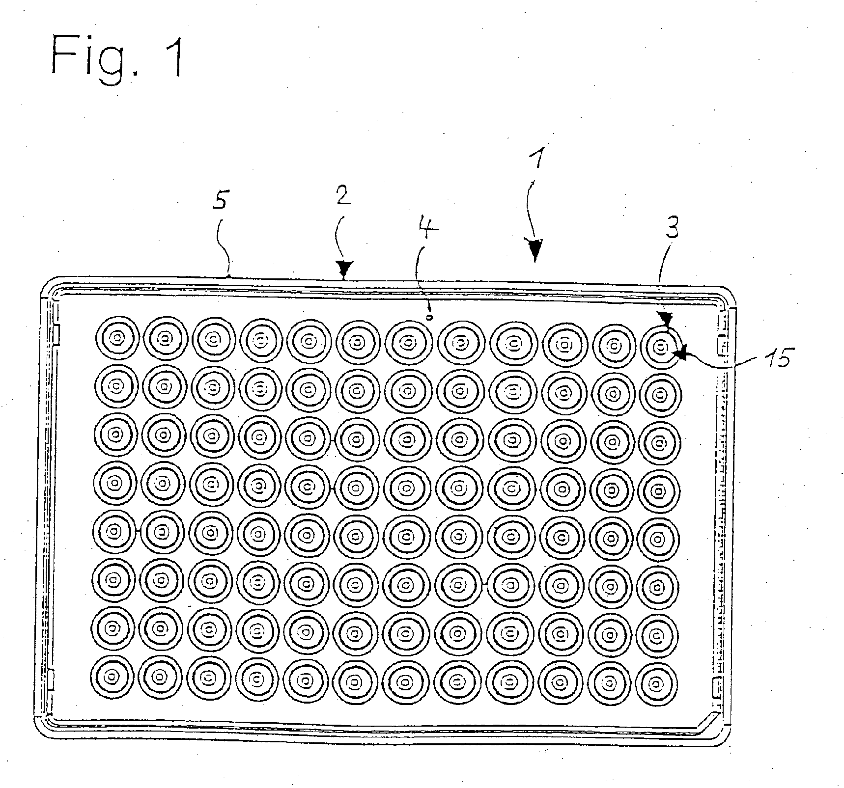
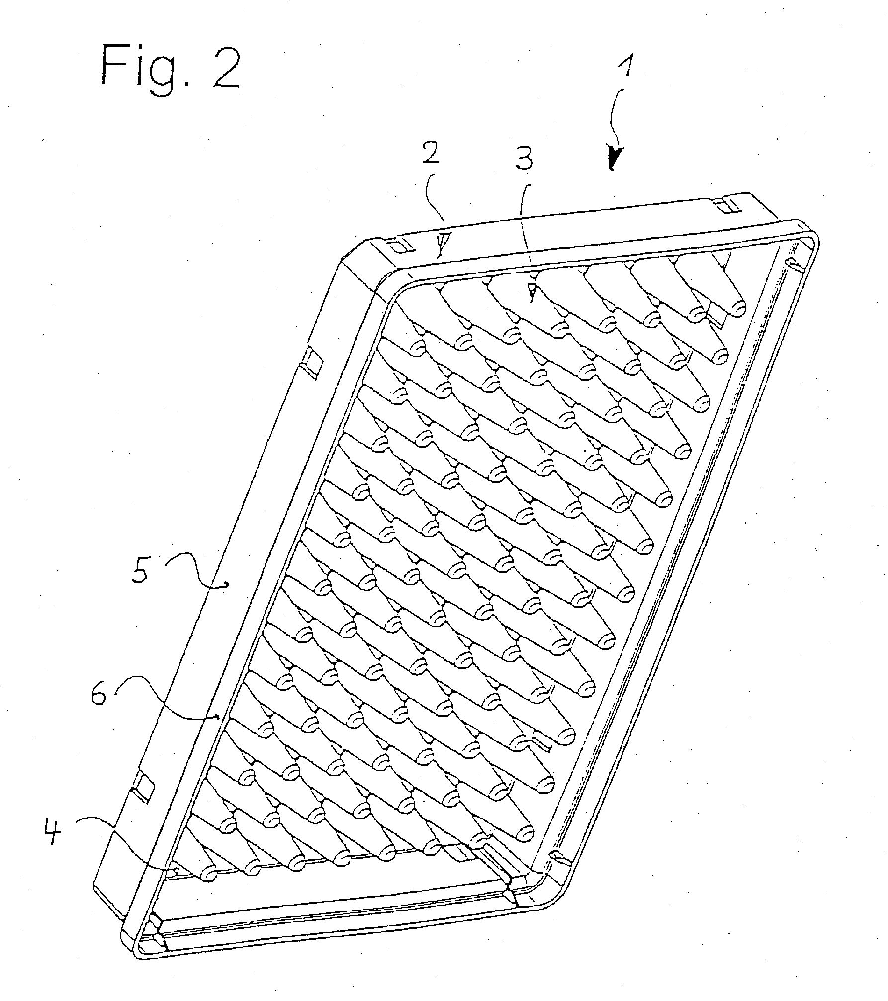
[0031]Referring to FIGS. 1 through 3, a microtitration plate 1 comprises a frame 2 and a multiplicity of receptacles 3. There is a total of 96 receptacles 3 in 8 columns and 12 rows.

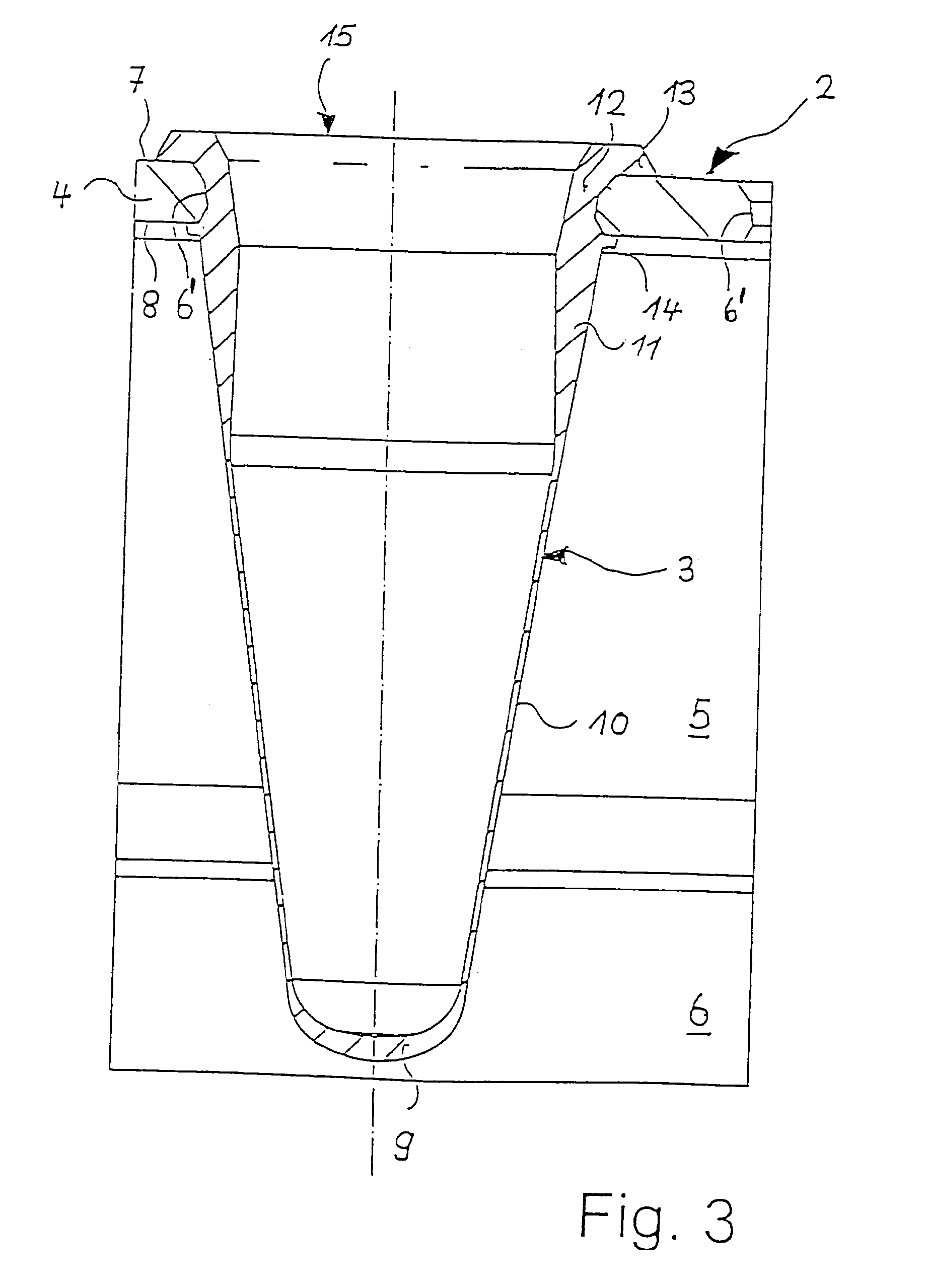
[0032]The frame 2 has a substantially rectangular plate 4 the outer edge of which is surrounded by a bordering 5 which protrudes approximately perpendicularly from the underside of the rectangular plate 4, i.e. beyond the receptacles 3. At bottom, the bordering 5 as is known has an expansion 6, which enables stacking on the upper surface of an appropriate microtitration plate 1.

[0033]The frame 2 has a total of 96 holes 6 in the rectangular plate 4. These have a course of cross-section which widens towards the upper surface 7 of the rectangular plate 4 in two portions of different conicity and towards the underside 8 of the rectangular plate 4 in a conical portion.

[0034]In a first molding step, the frame 2 is integrally molded from a plastic. It is preferred to use a high-purity polypropylene, possibly wi...


PUM

PropertyMeasurementUnit
thicknessaaaaaaaaaa
softening temperatureaaaaaaaaaa
temperatureaaaaaaaaaa

Abstract

A microtitration plate, having a frame made of a plastic which has a plate with a multiplicity of holes, and a multiplicity of receptacles made of the same plastic which are fixedly connected to the plate at the holes by directly molding them thereto, have a receiving portion protruding from the underside of the plate, and are accessible from the upper surface of the plate through apertures.

Description

RELATED APPLICATIONS[0001]This application is a continuation of pending U.S. application Ser. No. 10 / 393,911 filed Mar. 21, 2003, which is incorporated by reference herein.BACKGROUND OF THE INVENTION[0002]1. Field of the Invention[0003]The invention relates to a microtitration plate.[0004]2. Description of the Prior Art[0005]Microtitration plates are used for most varied microbiological, cell- breeding, and immunological techniques. In particular, microtitration plates are employed for the PCR or the breeding of microorganisms or cells.[0006]Microtitration plates have already been known which have a frame with a plate to which a multiplicity of receptacles are fixed which have a receiving portion protruding from the underside of the plate and are accessible from the upper surface of the plate through apertures. The receptacles are also referred to as “wells”. The current 96-receptacle microtitration plates have 8×12=96 receptacles in rows and columns. However, microtitration plates ...

Claims


Application Information

Patent Timeline
Patent Type & Authority Applications(United States)
IPC IPC(8): C12M1/40B01L3/00B29C45/16
CPCB01L3/5085B01L3/50851B29C2045/1659B01L2300/0829B29C45/16B01L2200/12
Inventor SEIPPEL, MARTIN
Owner EPPENDORF SE
Why Eureka
Try Eureka