Method for ion implant using grid assembly

a technology of ion implants and grid assemblies, applied in the field of solar cells, can solve the problems of low productivity, large use of power, and hot wafers

Active Publication Date: 2012-05-24
INTEVAC
View PDF24 Cites 24 Cited by
  • Summary
  • Abstract
  • Description
  • Claims
  • Application Information

AI Technical Summary

Benefits of technology

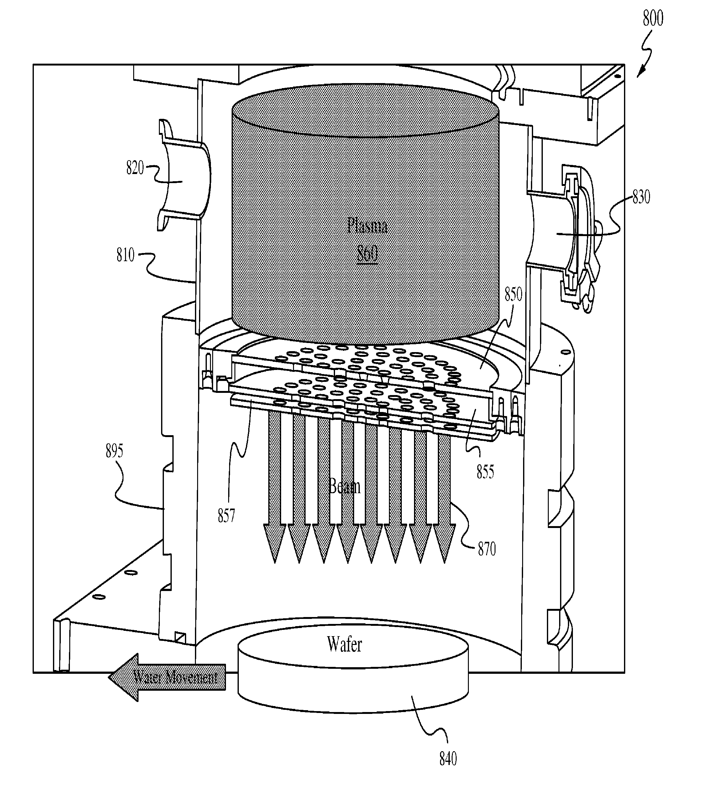
[0122]Another advantage of the present invention is that no subsequent diffusion is required, and thus, lower temperature anneal as low as 500° C. can provide enough activation and damage anneal that can be used for fabrication of a PV cell. Plasma grid implantation, due to its high productivity, can provide higher doses. Therefore, if only a portion of the dopant is activated, the desired resistivity and performance can still be achieved. Auto-annealing also may be employed, where the power of the beam is used to heat the substrate to such a desired temperature so that self-annealing can take place. Furthermore, balancing the elevated temperature of the substrate, masks, and grid assembly can be of major benefit in the general operation, control and metrology of the system.

Problems solved by technology

Additionally, it uses a lot of power in a small beam spot, and the wafer gets quite hot.
As a result, productivity is low.

Method used


Image

  • Method for ion implant using grid assembly
  • Method for ion implant using grid assembly
  • Method for ion implant using grid assembly

Examples


Embodiment Construction

[0044]The following description is presented to enable one of ordinary skill in the art to make and use the invention and is provided in the context of a patent application and its requirements. Various modifications to the described embodiments will be readily apparent to those skilled in the art and the generic principles herein may be applied to other embodiments. Thus, the present invention is not intended to be limited to the embodiment shown but is to be accorded the widest scope consistent with the principles and features described herein.

[0045]Furthermore, it is contemplated that any features from any embodiment can be combined with any features from any other embodiment. In this fashion, hybrid configurations of the illustrated embodiments are well within the scope of the present invention.

[0046]Various aspects of the disclosure may be described through the use of flowcharts. Often, a single instance of an aspect of the present disclosure may be shown. As is appreciated by ...


PUM

PropertyMeasurementUnit
resistanceaaaaaaaaaa
thicknessaaaaaaaaaa

Abstract

A method of ion implantation comprising: providing a plasma within a plasma region of a chamber; positively biasing a first grid plate, wherein the first grid plate comprises a plurality of apertures; negatively biasing a second grid plate, wherein the second grid plate comprises a plurality of apertures; flowing ions from the plasma in the plasma region through the apertures in the positively-biased first grid plate; flowing at least a portion of the ions that flowed through the apertures in the positively-biased first grid plate through the apertures in the negatively-biased second grid plate; and implanting a substrate with at least a portion of the ions that flowed through the apertures in the negatively-biased second grid plate.

Description

CROSS-REFERENCE TO RELATED APPLICATIONS[0001]This is a divisional application of U.S. patent application Ser. No. 12 / 821,053, filed on Jun. 22, 2010, and which claims priority from U.S. Provisional Application Ser. No. 61 / 219,379, filed Jun. 23, 2009, the disclosures of both of which are incorporated herein in their entireties.FIELD OF THE INVENTION[0002]The present invention relates generally to the field of solar cells and other large substrate implant applications. More particularly, the present invention relates to solar cell devices and methods of their formation.BACKGROUND OF THE INVENTION[0003]Although traditional beamline implantation of wafers can provide high power density, it has several disadvantages. For example, it only provides a single beamlet. Additionally, it uses a lot of power in a small beam spot, and the wafer gets quite hot. As a result, productivity is low.SUMMARY OF THE INVENTION[0004]In one aspect of the present invention, a plasma grid implantation system ...

Claims


Application Information

Patent Timeline
Patent Type & Authority Applications(United States)
IPC IPC(8): H01L21/223
CPCC23C14/042C23C14/48H01J37/32412H01J37/32422H01L21/2236H01L31/1876H01J37/3171H01J2237/0437H01J2237/184H01J2237/201H01L31/1864H01J37/185H01L31/068H01L31/0682H01L31/1804Y02E10/547Y02P70/50H01J37/317H01L31/042H01L31/18H01J2237/327H01J2237/3365
Inventor ADIBI, BABAKCHUN, MOON
Owner INTEVAC
Why Eureka
Try Eureka