Apparatus And Methods For Aspirating And Separating Components Of Different Densities From A Physiological Fluid Containing Cells

a technology of fluid tissue and components, applied in separation processes, laboratory glassware, centrifuges, etc., can solve the problems of creating surgical trauma, cumbersome and time-consuming access to bone marrow aspirate from the hip, and needle only moving linearly within the marrow spa

Active Publication Date: 2012-05-24
CERVOS MEDICAL LLC
View PDF2 Cites 42 Cited by
  • Summary
  • Abstract
  • Description
  • Claims
  • Application Information

AI Technical Summary

Benefits of technology

[0037]The combination of the aspiration and concentration apparatus allows a clinician the ability to access subcutaneous tissue in a less traumatic manner and then concentrate nucleated ce

Problems solved by technology

Surgeons who must cut through tissue to gain access to tissue create surgical trauma.
Accessing bone marrow aspirate from the hip is cumbersome and time consuming.
Consequently, most marrow aspiration needles are designed to only capture enough volume for these kinds of tests from the iliac bone in the hip.
Because the traditional aspiration needle is stiff, the needle can only advance linearly within the marrow space.
Since the hip bone is long and thin, once the traditional aspiration needle has penetrated cortical bone, the sharp and stiff instrument has the potential to penetrate through the other side of the cortical bone, resulting in significant trauma.
Since the trocar is made of a stiff material, once inside the spongy bone, the needle assembly can only go straight, thus requiring multiple punctures to obtain the required volume of aspirate.
A traditional marrow aspi

Method used


Image

  • Apparatus And Methods For Aspirating And Separating Components Of Different Densities From A Physiological Fluid Containing Cells
  • Apparatus And Methods For Aspirating And Separating Components Of Different Densities From A Physiological Fluid Containing Cells
  • Apparatus And Methods For Aspirating And Separating Components Of Different Densities From A Physiological Fluid Containing Cells

Examples


Embodiment Construction

[0072]A description of example embodiments of the invention follows.

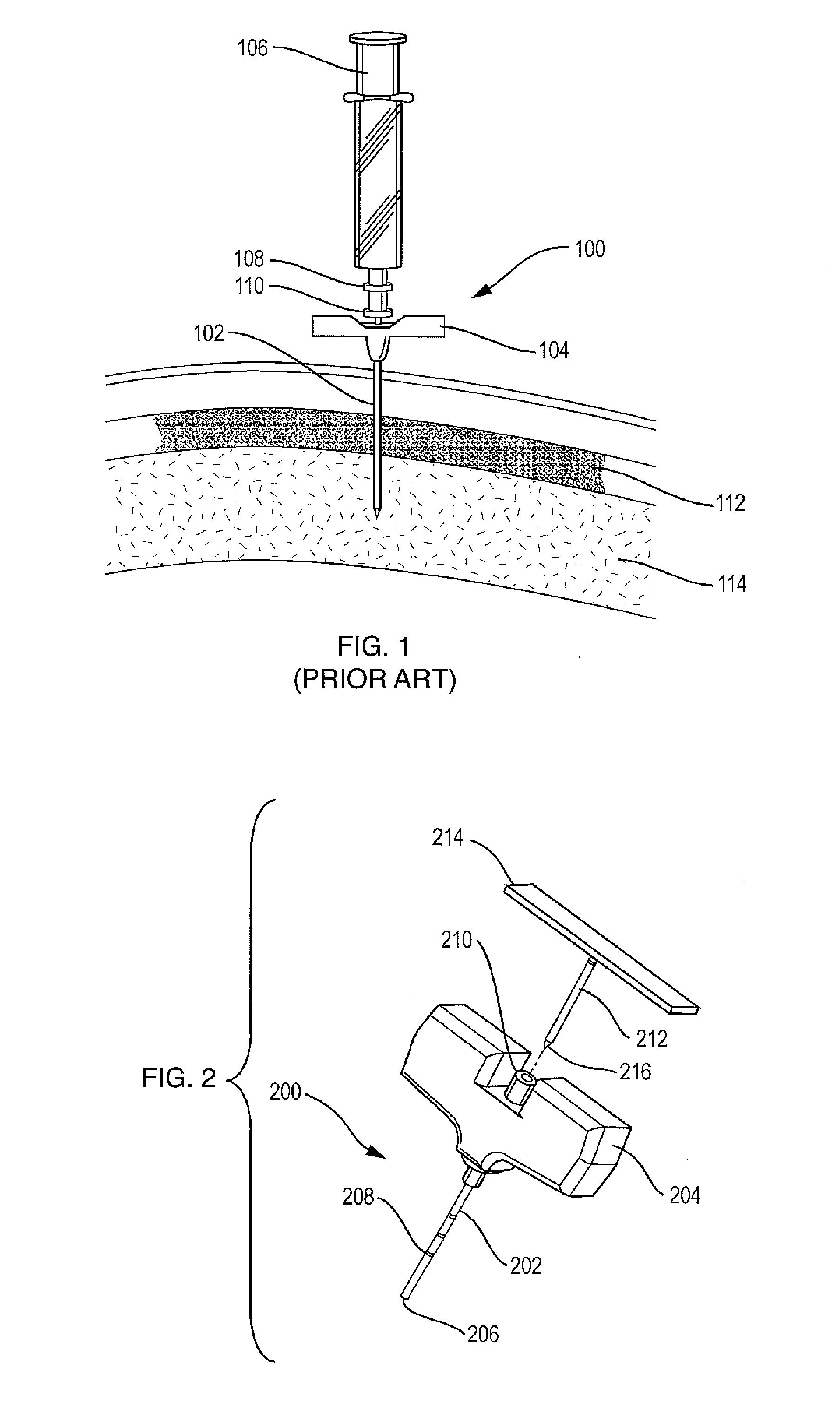
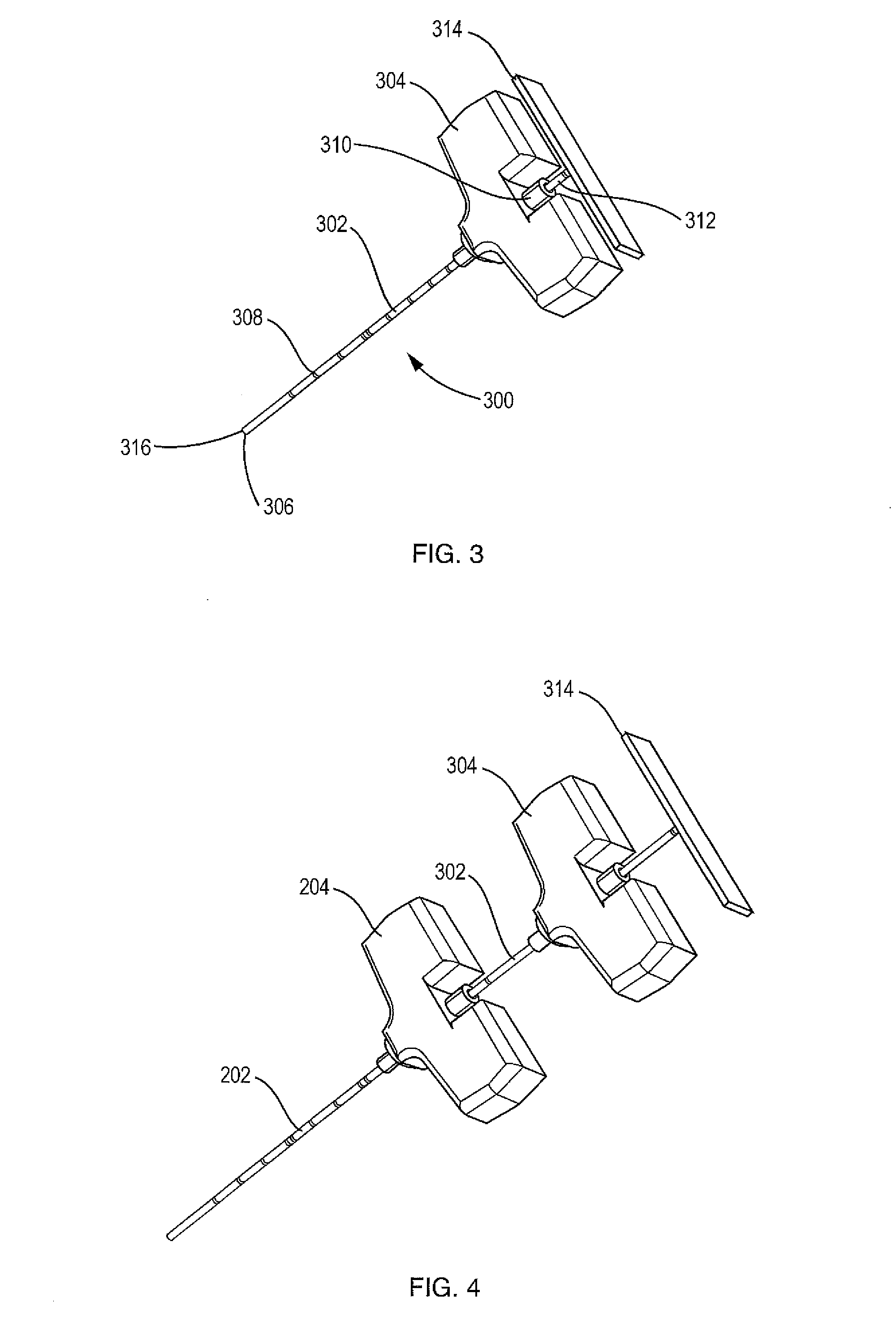
[0073]With respect to aspirating bodily fluids, an aspiration apparatus is provided that allows for different lengths of needle assemblies to fit coaxially together by removing the trocar or stylet of the previous needle assembly. The outer diameter of the cannula of each successive needle assembly is smaller and the length is longer than the inner diameter and length, respectively, of the cannula of the previous needle assembly. Beyond diameter and length, each successive needle assembly can have other characteristics such as flex and sharpness. Many different diameters, lengths, and stiffness can be incorporated into the design and the design can incorporate two or more needle assemblies in order to make apparatus designed for certain applications. For example, assemblies designed for use in tendon and ligament repair may be different in length, stiffness, or some other material property, such as lubricity, than t...


PUM

PropertyMeasurementUnit
Fractionaaaaaaaaaa
Fractionaaaaaaaaaa
Densityaaaaaaaaaa

Abstract

A system for separating components defining a cavity for receiving the fluid. The system further includes a rigid insert slidably disposed in the cavity, the insert including a funnel-shaped upper portion and a hole therethrough. The insert has a density such that upon centrifugation a selected component of the fluid resides within the upper portion of the insert. A bone marrow aspiration device includes an introducer needle assembly and an aspiration needle assembly. The introducer needle assembly includes an introducer cannula and a removable trocar. The aspiration needle assembly includes a flexible aspiration cannula and a flexible stylet. The length of the aspiration cannula is substantially greater than the length of the introducer cannula. The aspiration needle assembly is receivable in the introducer cannula when the trocar is removed from the introducer needle assembly. The aspiration cannula forms a channel for aspirating bone marrow when the stylet is removed.

Description

RELATED APPLICATIONS[0001]This application claims the benefit of U.S. Provisional Application No. 61 / 182,437, filed on May 29, 2009.[0002]The entire teachings of the above application are incorporated herein by reference.TECHNICAL FIELD[0003]This invention relates to methods and apparatus for the aspiration of a fluid tissue and separation of the fluid tissue into different components of different densities. The invention has particular utility for the separation of bone marrow aspirate, adipose tissue and blood.BACKGROUND OF THE INVENTION[0004]Surgeons who must cut through tissue to gain access to tissue create surgical trauma. The ability to access subcutaneous tissue with minimal trauma is a benefit to the clinician and patient. With the aging population and rising health care costs, any therapy that is less invasive, more effective, and less expensive has the potential to change the practice of medicine. Surgeons are continually looking for means to gain access to a broad cross ...

Claims


Application Information

Patent Timeline
IPC IPC(8): B01D43/00B04B7/12B04B15/00
CPCA61B10/025A61B2010/0258A61M1/3693A61M2202/10B01L2400/0478B01L3/50215B01L3/50825B01L2200/026B01L2300/046B01D17/0217B01L3/5021B01L2200/025B01L2300/042B01L2300/048B01L2300/0609B01L2300/0848B01L2300/0851B01L2300/0858B04B1/08B04B11/04
Inventor DUFFY, NEIL FRANCISCHABOT, JEFFREY R.
Owner CERVOS MEDICAL LLC
Why Eureka
Try Eureka