Post anchoring devices and methods

a technology of post anchoring and sleeve, which is applied in the direction of building components, building repairs, foundation engineering, etc., can solve the problems of unsightly supporting triangular brackets, superior aesthetic solutions designed to conceal fasteners, and previously possessed lower strength characteristics, so as to improve performance, reduce hardware requirements and the time to install the device using this method, the effect of boosting performan

Inactive Publication Date: 2012-05-31
BERGMAN RICHARD
View PDF11 Cites 31 Cited by
  • Summary
  • Abstract
  • Description
  • Claims
  • Application Information

AI Technical Summary

Benefits of technology

[0030]The use of a tubular member in the present invention creates a rigid and strong joint at the precise location where most of the leverage and lateral force against a post is concentrated. The tubular member also provides a large surface area for frictional engagement between its inner and outer walls and the material of the post, thereby generating significant frictional holding power. This increased holding power and a more rigid union with the base provides an effective mechanism for mounting a post to a surface in an aesthetically pleasing manner so as to avoid the need for externally visible hardware by enabling the base and fasteners to be installed first and inside the outer periphery of the post walls. This characteristic allows the base to be sized smaller or larger, depending on preference, than the periphery of the post. The combination of the characteristics of this invention as described above offer a superior solution to addressing the challenge of maximizing strength and aesthetic value than prior art devices.
[0046]The results of the tests conducted on a rail system and method using the device without the horizontal barrel bolt technique have been shown to meet the building code minimum standards for residential guard rails. And other comparative test results that isolate the performance of single posts using the device with and without the barrel bolt confirm increased load resistance with the barrel bolt. Therefore, it is certain that a rail system and method using the device with the barrel bolt will provide an even higher level of performance.

Problems solved by technology

Alternatively, superior aesthetic solutions designed to conceal fasteners have heretofore possessed lower strength characteristics and often require unsightly supporting triangular brackets to stiffen the post to surface connection.
These types of brackets are functional only and not aesthetically pleasing.
While functional, these devices are not aesthetically appealing.
While the Timko device provides a stiff, secure union between post and mounting surface, it is attached to the outside of the post and has numerous visible fasteners that detract from the overall aesthetical appearance.
While the Nicholas device conceals the fasteners, boring is required in both the post and the floor surface.
It is also unsuitable for outdoor applications because the base of the post would be in direct contact with the mounting surface and subject to moisture and water damage.
Although the device does conceal all fasteners, it is not suitable for mounting on to surfaces that are not as hard as concrete, such as wood, because the base is secured by a wedge bolt that must be placed into a hole bored into concrete or like material.
This device hides all fasteners, but without bracing, the unsupported newel posts are wobbly because the strength of the post to base connection is dependent upon the integrity of the narrow lag screw.
The inherently narrow cross sectional dimensions of the lag screw necessarily means that it can never provide the degree of stiffness that is ultimately required for applications outside of a unitary railing system.
In addition, a challenge exists for meeting building code requirements for wood posts because the physical properties of wood, such as specific gravity, grain pattern, moisture content and knot locations vary greatly.
As a result of this range of variability among wood species, it is not sufficient that a wood guardrail merely meet the lower design loads specified in the building code.
However even if a single post can not provide load resistance of 500 lbs it does not necessarily mean that a guardrail system using such a post would fail to meet the building code standards.
Nonetheless, single posts rather than complete post and rail systems are often subjected to this test load as a worst case scenario because it stands to reason that if a single post can with stand such a load, the complete railing system will provide greater resistance—subject of course to rail span limits based on maximum distributive loads created between directional changes.
And none of the methods to which the academics refer as being able to meet the building codes are surface mounted connections between post and deck.
However the aesthetic appearance of a post that is secured to the outside band board does not appeal to many homeowners and architects or builders.
The less desirable aspects of joist connected posts are: decking boards must be notched if posts are set inside the deck framing; when posts are attached to the outside face of deck framing they appear less attractive and require two adjacent posts at exterior corners; railing sections between posts are located beyond the vertical plane of the deck's perimeter which is unappealing and creates a potentially larger gap between the bottom rail and the decking surface; alternatively railing sections can be attached to the inside face of the posts but this creates a crude aesthetic appearance; and wood to wood contact leaves posts and joists vulnerable to water damage in areas with wetter climates leading to faster deterioration and higher maintenance costs.
Surface mounted anchors will almost always offer lower top end lateral load resistance than joist mounted posts, and finding ways to maximize their strength while maintaining their intrinsic aesthetic appeal remained a great challenge in this field of art.
They are large, bulky and unsightly apparatuses which have low aesthetic value.
As well, they do not necessarily pass the building code and so their use is most often confined to non-building code applications.

Method used


Image

  • Post anchoring devices and methods
  • Post anchoring devices and methods
  • Post anchoring devices and methods

Examples


Embodiment Construction

[0063]Reference will now be made in detail to the present preferred embodiments of the invention, examples of which are illustrated in the accompanying drawings. The invention disclosed herein may be practiced in embodiments in many different forms. Shown in the drawings and described herein are preferred embodiments of the present invention. However, it is understood that the present disclosure is an exemplification of the principles of the invention and does not limit the invention to the illustrated embodiments.

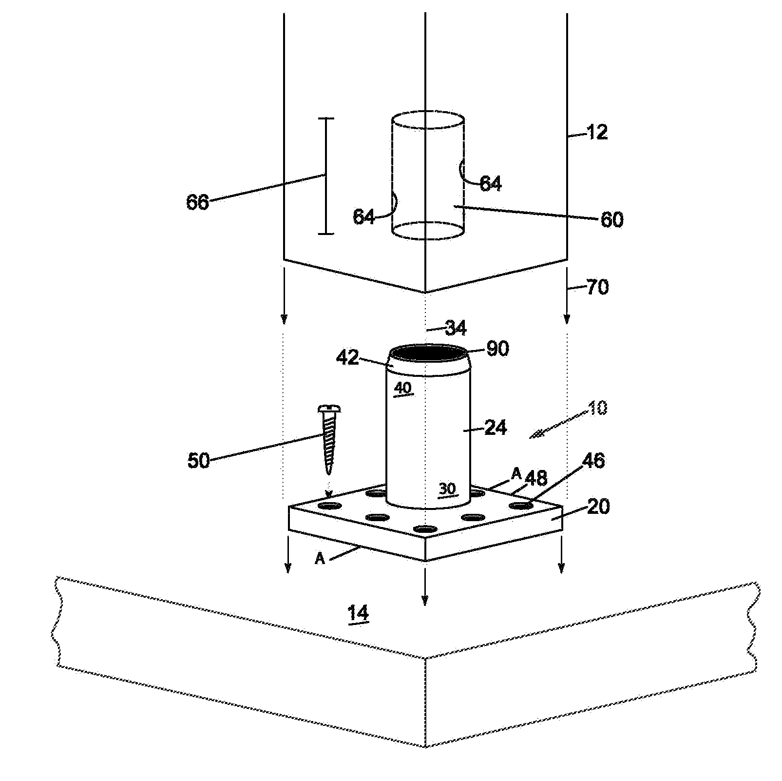
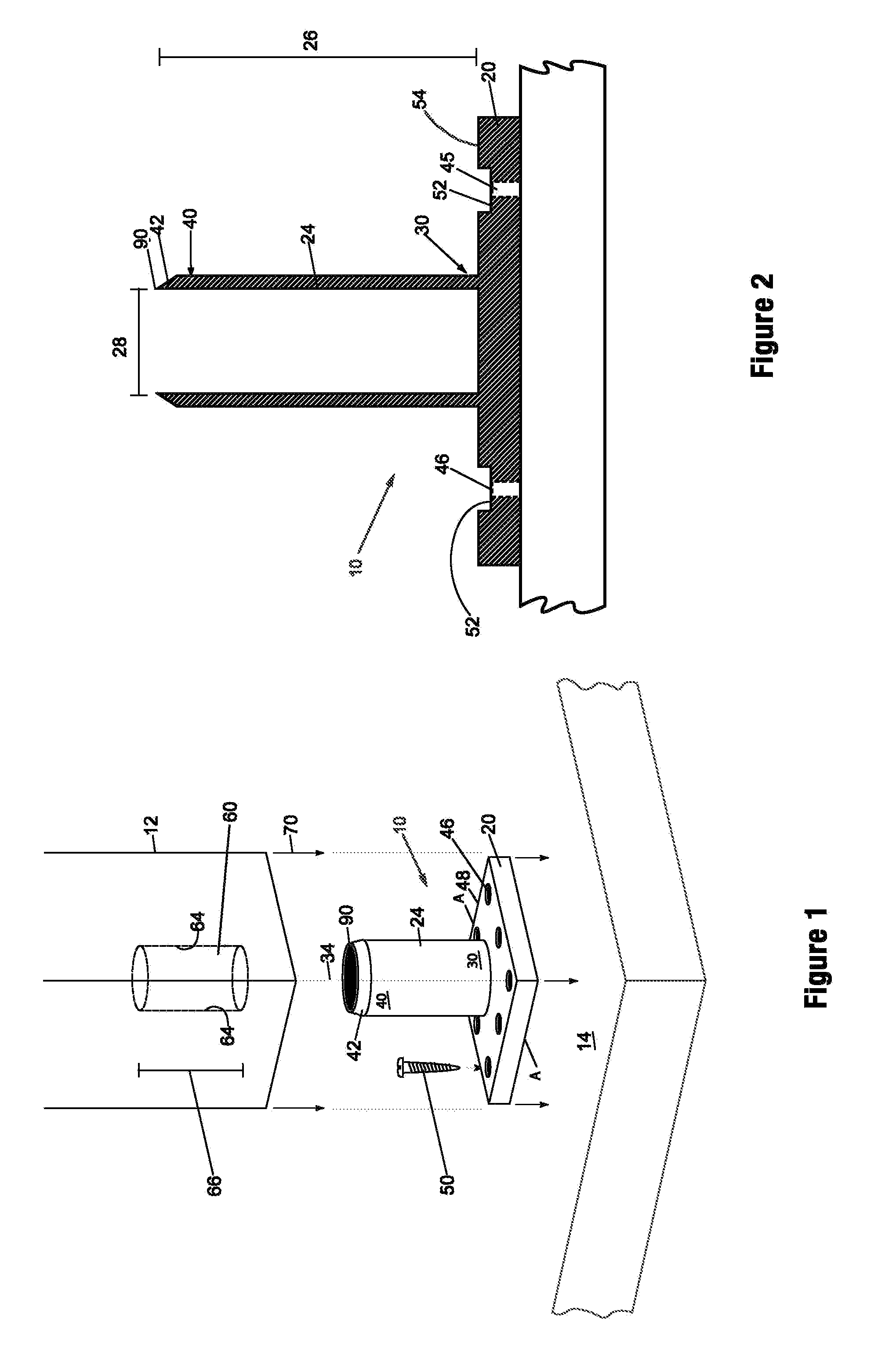
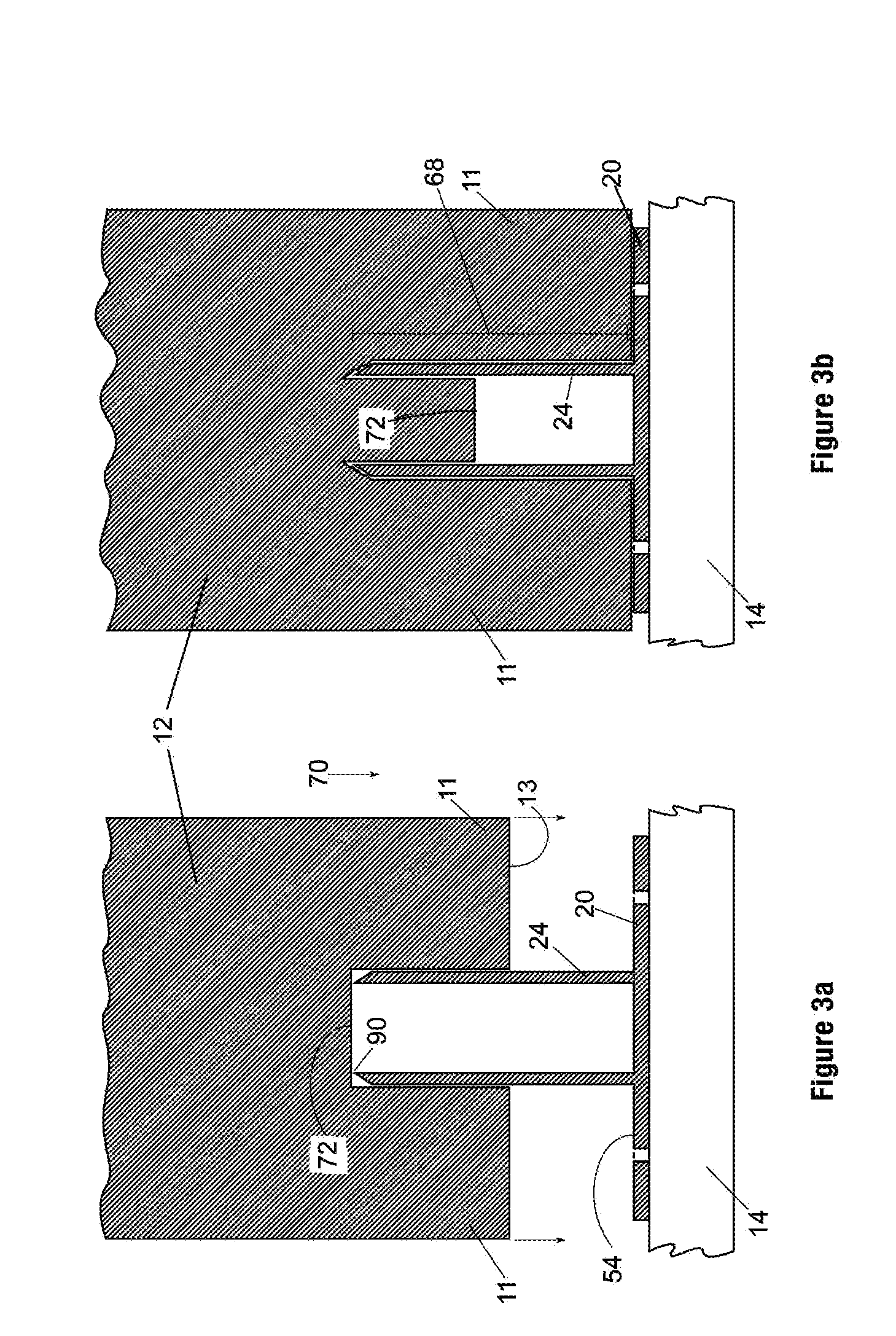
[0064]Referring to FIGS. 1-3, there is depicted an embodiment of the present invention: a post anchoring device 10 for anchoring a post 12 to a surface 14. Device 10 comprises a planar base member 20 and an elongate tubular member 24 that is preferably cylindrical. As used herein, the word “tubular” means having the form or shape of a thin-walled hollow body. The tubular member is connected at a base end 30 to the base member. Preferably, longitudinal axis 34 of the tubula...


PUM


Abstract

A post anchoring device for anchoring posts used in fence, deck, balcony and railing applications to a surface, the device comprising a base member capable of being connected to the surface, and an elongate, preferably cylindrical, tubular member having a base end and a terminal end, the base end being connected to the base member and the terminal end being remote from the base member such that the post may be impaled upon the tubular member by a user. The walls of the tubular member at the terminal end may be beveled to provide a cutting edge for cutting into the post to facilitate the impalement of the post. The base member may include a peripheral flange with a peripheral edge for abutting the end of the post thereby defining a cavity in which fasteners or other hardware may be concealed from sight for an aesthetically pleasing result.

Description

BACKGROUND OF THE INVENTION[0001]1. Field of the Invention[0002]The invention relates to fastening systems and methods used for securing posts and the like to mounting surfaces, and more particularly to post anchoring devices and methods for anchoring wood, fiber or other synthetic composite material posts used in fence, deck, balcony and railing applications to wooden, concrete, fiberglass, vinyl or other surfaces.[0003]2. Description of the Related Art[0004]There is a need to provide a mechanism by which posts can be secured to generally horizontal surfaces in such a way as to meet or exceed the functional requirements of strength and elimination of rot, and at the same time address aesthetic concerns surrounding the visibility and unsightly nature of the anchoring device and the fasteners used therein.[0005]Strength of design is particularly important for an unsupported run of railing or fence posts that separate areas differing in elevation. Equally important is the need to ensu...

Claims


Application Information

Patent Timeline
Patent Type & Authority Applications(United States)
IPC IPC(8): E02D27/42E04B1/38
CPCE04F11/1812E04H17/22E04H12/2261E04H17/009
Inventor BERGMAN, RICHARD
Owner BERGMAN RICHARD
Why Eureka
Try Eureka