Refacing tools and methods

a technology for refacing tools and methods, applied in the direction of manufacturing tools, turning machine accessories, portable lathes, etc., can solve problems such as failure of connection, repeated face-to-face contact and wear, and failure of connection

Active Publication Date: 2012-05-31
MAGNA SONIC STRESS TESTERS
View PDF19 Cites 15 Cited by
  • Summary
  • Abstract
  • Description
  • Claims
  • Application Information

AI Technical Summary

Benefits of technology

[0011]Because of the advantages associated with high torque connections, the disadvantages associated with refacing high torque connections, and the

Problems solved by technology

If the condition of the face / seal is not smooth, it can leak and result in a connection failure.
In addition, over-torque of the connection can over-stress the threads and shoulder and cause a connection failure.
If, however, a face is flawed or damaged with scratches, nicks, or other irregularities, it must be refaced prior to being used.
During use of the pipe and assembly components, connections may be repeatedly made up and broken resulting in repeated face to face contact and wear.
The resulting wear may result in sealing faces that are scored, nicked, or scratched or that no longer present a planar surface at right angles to the longitudinal axis of the pipe.
When such conditions occur, the face-to-face contact may not form a proper pressure seal, thereby leading to connection failures.
Prior attempts to recondition the faces of pipe have employed methods that are costly or inconvenient and equipment that is expensive and / or unavailable in the field.
However, re-tooling in a machine shop involves expensive and inconvenient transportation costs to transport the damaged / flawed pipe to the shop.
Maintaining equal pressure can be difficult for an operator resulting in crooked faces that are not within acceptable tolerances.
In addition, even if equal pressure is applied, the refaced faces may still be crooked with respect to the axis of the threads if the tool is operated out of line with the axis of the threads.
In addition, the tungsten carbide cutters can chip, causing irregularities on the face.
Frequently, in high-torque connections used in drilling, the threads sharpen during repeatedly making up and breaking out the connection, resulting in threads that are raised and narrow.
These sharpened threads impede the Lightning Refacer from easily sliding onto the threads.
This process is time consuming and can affect the subsequent accuracy of the reface.

Method used


Image

  • Refacing tools and methods
  • Refacing tools and methods
  • Refacing tools and methods

Examples


Embodiment Construction

[0032]Exemplary embodiments are herein described in detail with reference to the figures.

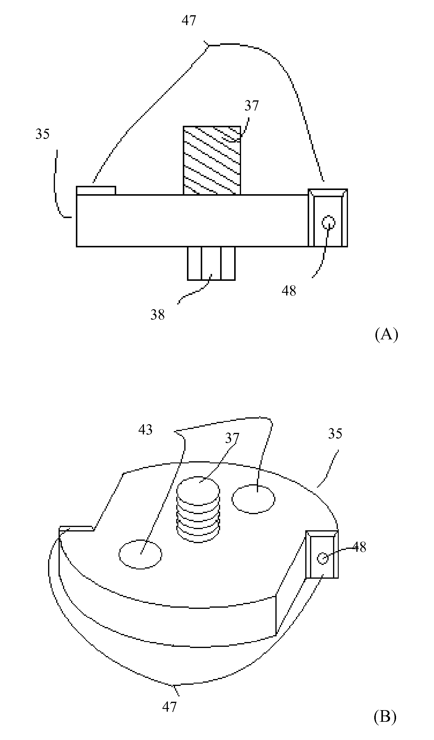
[0033]The apparatuses and methods described herein are for refacing the ends of high-torque pipe and bottom hole assemblies. Bottom hole assemblies refer to the equipment used below the drill pipe to drill a well. For example, bottom hole assemblies may include: drill collars, weight pipe, stabilizers, x-over subs, bit subs, reamers, drilling jars, cushion subs, directional tools, and string floats. For purposes of this specification, “pipe” refers to both drill pipe and bottom hole assembly components. FIGS. 1 and 2 illustrate the ends or connections of high-torque pipe.

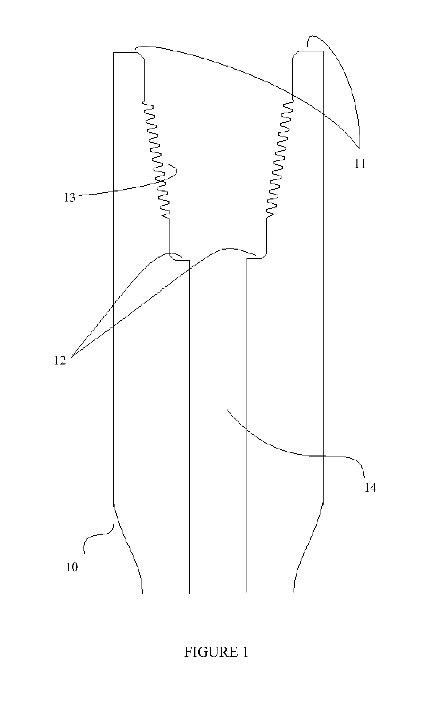
[0034]FIG. 1 illustrates a box-end of a pipe tool joint 10. A “box connection” refers to the female connection on the drill pipe. The box-end has a primary face 11, a torque-stop face 12, and a threading 13. Once a connection is made, material may flow through the inner portion 14 of the pipe.

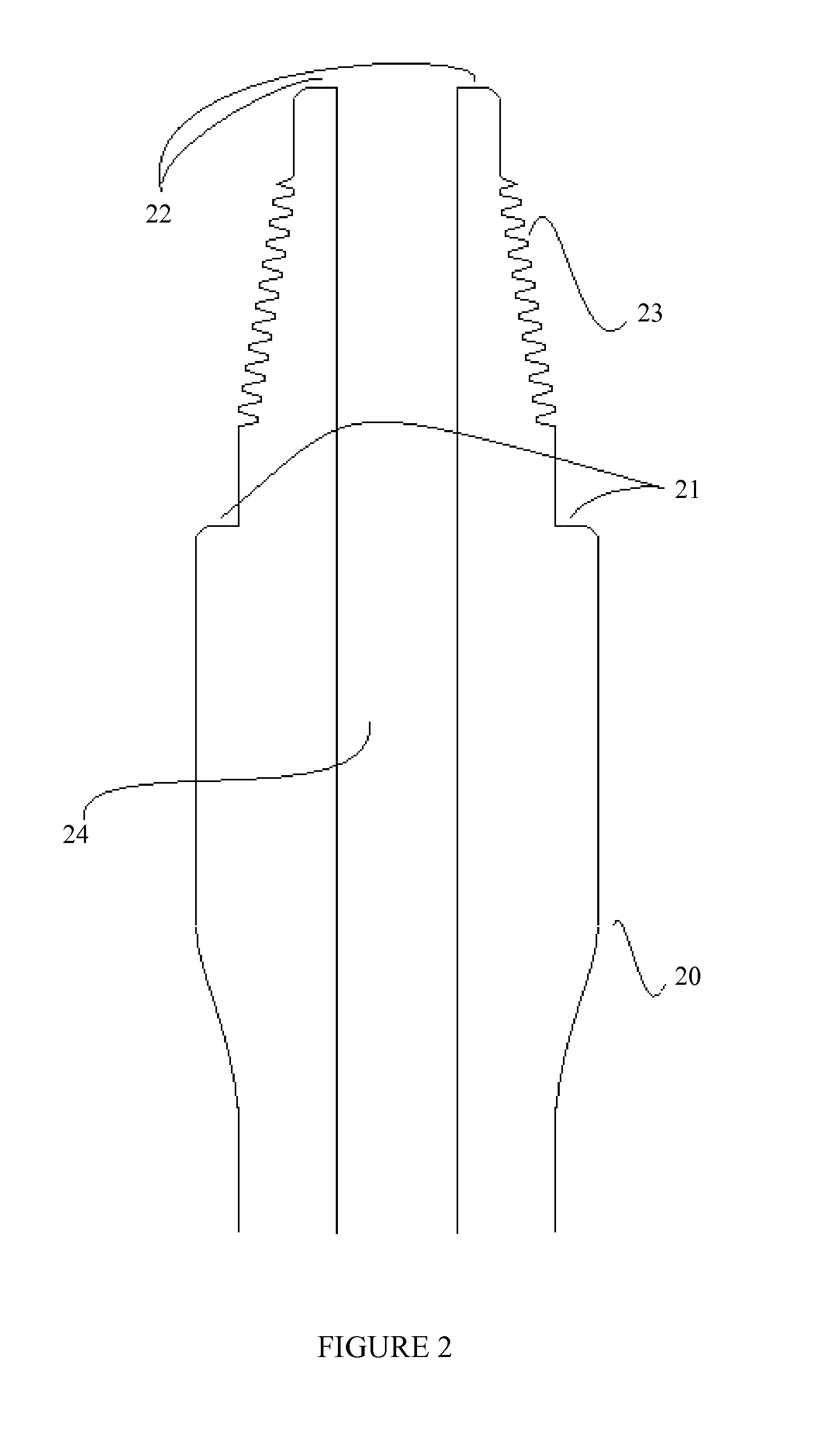
[0035]FIG. 2 illustrates a pin-end o...


PUM

PropertyMeasurementUnit
Lengthaaaaaaaaaa
Torqueaaaaaaaaaa

Abstract

A high-torque connection refacing tool, including a shaft, a mandrel, a primary face plate, and a torque-stop face plate.

Description

BACKGROUND[0001]1. Field of Invention[0002]The invention relates to apparatuses for refacing a pipe connection and methods of refacing a pipe connection. The tools and methods described herein are particularly useful in the field of refacing drill pipe.[0003]2. Description of Related Art[0004]Tubular members, such as those used in oilfield applications, are often joined by threaded rotary shoulder connections. For example, rotary shoulder connections are used in the oil field to join sections of drill pipe and other related assemblies together. In a rotary shoulder connection, the shoulders, also referred to as faces and seals, are pressed together by the threads. The thread flanks jack against each other pushing the shoulders into each other. The shoulders provide strength and integrity to the connection and also work as seals to seal fluid pumped through the inside of the pipe. In a conventional rotary shoulder connection, each piece of pipe to be connected has one face / seal. If t...

Claims


Application Information

Patent Timeline
IPC IPC(8): B23B5/16B23B1/00B23B3/22
CPCB23B5/162B23B5/163B23B2215/72B23B2260/078B24B7/16Y10T82/10B23B2215/68B23B2220/08Y10T82/2529Y10T82/22Y10T82/2522B23B5/16B23B41/12
Inventor MANWARING, KEVIN K.
Owner MAGNA SONIC STRESS TESTERS
Why Eureka
Try Eureka