Eureka AIR delivers breakthrough ideas for toughest innovation challenges, trusted by R&D personnel around the world.

All-Optical, Phase Sensitive Optical Signal Sampling

a phase sensitive, all-optical technology, applied in electromagnetic receivers, electromagnetic transmission, transmission monitoring, etc., can solve the problems of affecting the accuracy of the signal, and reducing so as to reduce the number of certain components. , the effect of relatively high cos

Active Publication Date: 2012-05-31
EXFO
View PDF9 Cites 15 Cited by
  • Summary
  • Abstract
  • Description
  • Claims
  • Application Information

AI Technical Summary

Benefits of technology

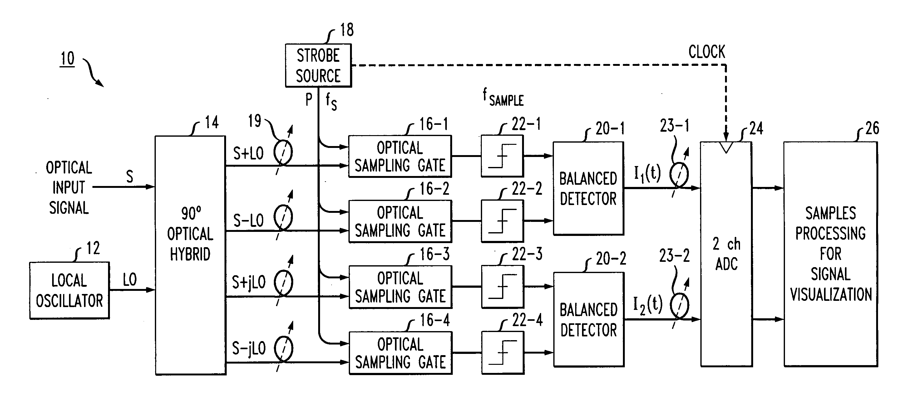
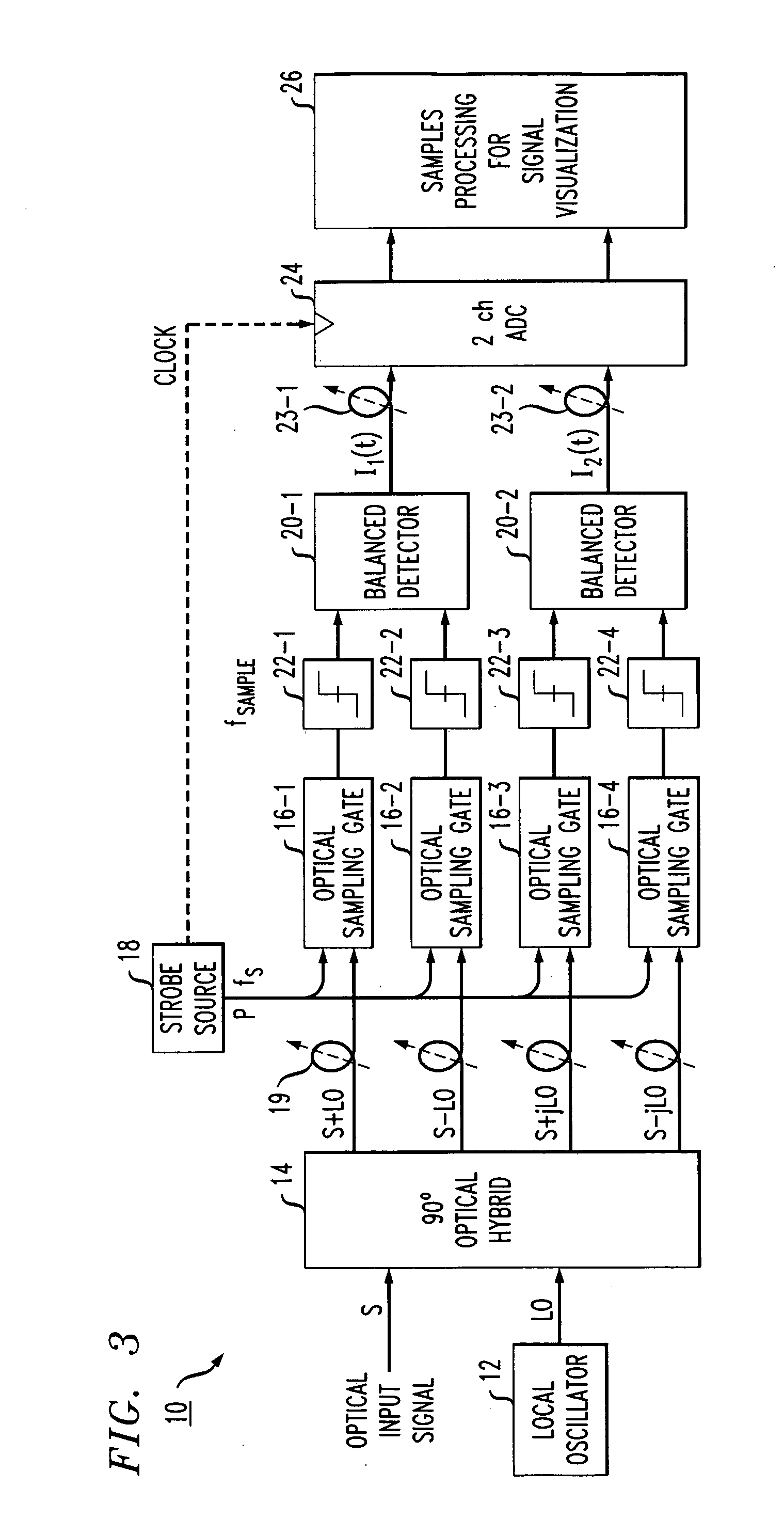
[0022]In a particular embodiment of the present invention, the strobe signal is applied as an input to the optical hybrid (combined on the same signal path as either optical input signal S or reference signal LO (preferably, reference signal LO), rather than applying the strobe signal as a direct input to the sampling gate. In this arrangement, an optical signal is used as the strobe signal. By passing the strobe signal through the same optical element (i.e., optical hybrid) as signals S and LO, the need for adjusting the relative timing between these signals at the input of the sampling gate is eliminated since all signals will propagate along the same optical signal path.
[0025]A polarization-multiplexed embodiment of the present invention may be utilized to reduce the number certain, relatively expensive components that are needed to process the set of output signals from the optical hybrid.

Problems solved by technology

However, implementation was difficult and with the advent of erbium-doped fiber amplifiers (EDFAs), the commercial deployment of coherent detection systems was delayed.
The need for a “repetitive” waveform is a fundamental limitation of the equivalent-time sampling approach.
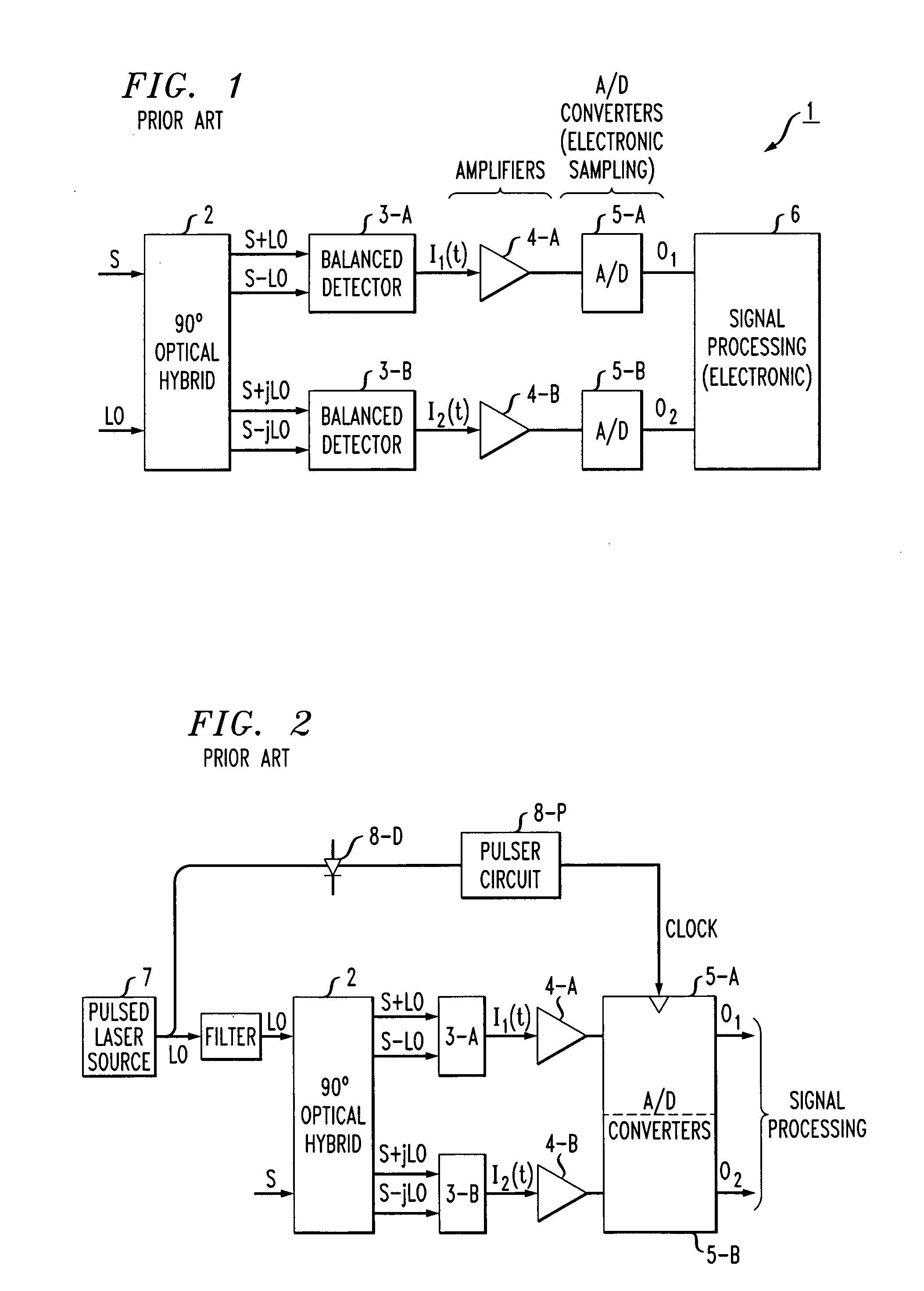
Prior art coherent detection arrangement 1 as shown in FIG. 1 employs an electronic sampling technology that has at least one significant drawback—the bandwidth limitation of the electronic A / D converter and sampling circuits (i.e., for “electronic sampling”).
There remains, however, a few drawbacks with this hardware implementation, particularly related to strict wavelength requirements on the pulsed sampling laser source.
This requirement complicates the possibility of providing an optically broadband measurement system, since if the wavelength of the optical input signal is changed, the pulsed sampling laser source must also adapt its wavelength.
Indeed, there are no tunable commercial, suitably low-phase-noise short-pulse sources capable of offering the typically >500 MHz sampling rate that is most desirable for robust IF recovery algorithms.

Method used


Image

  • All-Optical, Phase Sensitive Optical Signal Sampling
  • All-Optical, Phase Sensitive Optical Signal Sampling
  • All-Optical, Phase Sensitive Optical Signal Sampling

Examples


Embodiment Construction

[0035]As discussed above, optical sampling technologies can provide extremely high bandwidth measurement capabilities, depending on the temporal width of the strobe pulses (also referred to herein as “gating” pulses) used to form the sampling signal. In this regard, measurement bandwidths as high as 500 GHz have been demonstrated, and optical sampling has been implemented using a wide variety of nonlinear phenomena and hardware arrangements.

[0036]A key aspect to the present invention is that in addition to providing a high measurement bandwidth, the optical gating preserves the relative phase relationship between optical input signal S and reference signal LO throughout the entire sampling process, where the relative phase relationship is not affected by pulse-to-pulse phase instabilities of the strobe source. In a preferred embodiment of the present invention, this phase preservation is an inherent consequence of utilizing a nonlinear optical system as the sampling component. In th...


PUM


Abstract

An optical sampling arrangement for high-speed measurement of the time-varying electric field of an optical input signal utilizes coherent mixing of the optical input signal with a reference laser source in a phase-diverse optical hybrid solution, followed by optical sampling of the coherently-mixed fields at the output of the optical hybrid. The generated streams of optical samples are then detected and signal processed in order to reconstruct a sampled version of the electric field of the original optical input signal.

Description

CROSS-REFERENCE TO RELATED APPLICATIONS[0001]This application claims the benefit of U.S. Provisional Application No. 61 / 208,427, filed Feb. 23, 2009, which is herein incorporated by reference.TECHNICAL FIELD[0002]The present invention relates to high-speed measurement of the electric field of optical signals. In particular, this invention relates to a coherent optical sampling arrangement that is particularly well-suited for measurement of the complete electric field (both phase and amplitude) of an optical input signal normally comprising optically-encoded data.BACKGROUND OF THE INVENTION[0003]Recent advances in the field of optical communication with new, more complex, data modulation formats as a key technology has created a need for optical waveform characterization tools that are capable of extracting more information from the waveform than simply its power as a function of time. Encoding data onto an optical carrier by modulation of both the optical field phase and amplitude h...

Claims


Application Information

Patent Timeline
IPC IPC(8): H04B10/08
CPCH04B10/64H04B10/60
Inventor WESTLUND, MATHIASSKOLD, MATSSUNNERUD, HENRIKANDREKSON, PETERRUCHET, BERNARD
Owner EXFO
Why Eureka
Eureka Blog
Learn More