Method for spreading fiber bundles, spread fiber sheet, and method for manufacturing a fiber-reinforced sheet

a technology of fiber bundles and fiber reinforcements, applied in the direction of instruments, other domestic objects, transportation and packaging, etc., can solve the problems of more meandering and tangling of fibers, and achieve the effects of wide spread width, excellent straightness, and uniform thickness

Active Publication Date: 2012-05-31
FUKUI PREFECTURE
View PDF8 Cites 31 Cited by
  • Summary
  • Abstract
  • Description
  • Claims
  • Application Information

AI Technical Summary

Benefits of technology

[0027]The present invention is provided with the above configuration so that a set of regions Si each including a pair of a fiber-spreading region Ai (i=1, . . . , n) and an expansion region Bi (i=1, . . . , n) are arranged in a movable region M set so that the fibers of the fiber bundle can move in the width direction, the fiber-spreading region Ai moving the fibers in the width direction while bending the fibers by letting a fluid pass through the fiber bundle, thereby spreading the fiber bundle to a spread width Wi (i=1, . . . , n), and the expansion region Bi which is set on the upstream side in the feeding direction corresponding to the fiber-spreading region Ai and in which the width of the fiber bundle expands toward the end with movement of the fibers in the width direction in the fiber-spreading region Ai, by performing pre-spreading in which a movement phenomenon in the width direction caused by distribution of the fibers of the fiber bundle occurring in the fiber-spreading region Ai is made to act on the expansion region Bi on the upstream side so as to gradually move the fibers in the width direction, an action of uniformly distributing the fibers in the fiber-spreading region Ai and of expanding the spread width to a predetermined width can be continuously performed, and the fiber bundle can be spread wide in a state of favorable fiber distribution.
[0028]As in the above-described prior-art documents, if wide fiber-spreading is performed by a method in which fiber-spreading regions are continuously set, spreading is continued in a state affected by uneven adhesion or entanglement of the fibers, and the uneven adhesion or entanglement of the fibers have prevented uniform distribution of the fibers, but in the present invention, since a plurality of the region sets Si in which the expansion region Bi is set on the upstream side of the fiber spreading region Ai is arranged, fiber-spreading will be able to be gradually performed while the fiber bundle is untangled.
[0029]That is, in the movable region, since movement of the fibers in the width direction by being sandwiched by a feed roller or the like is not obstructed, the fibers of the fiber bundle can move ...

Problems solved by technology

However, the carbon fiber bundle having an increased number of fibers has a defect tha...

Method used


Image

  • Method for spreading fiber bundles, spread fiber sheet, and method for manufacturing a fiber-reinforced sheet
  • Method for spreading fiber bundles, spread fiber sheet, and method for manufacturing a fiber-reinforced sheet
  • Method for spreading fiber bundles, spread fiber sheet, and method for manufacturing a fiber-reinforced sheet

Examples


example

Example 1

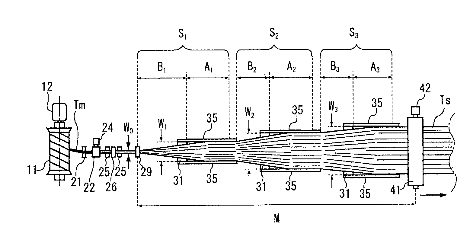
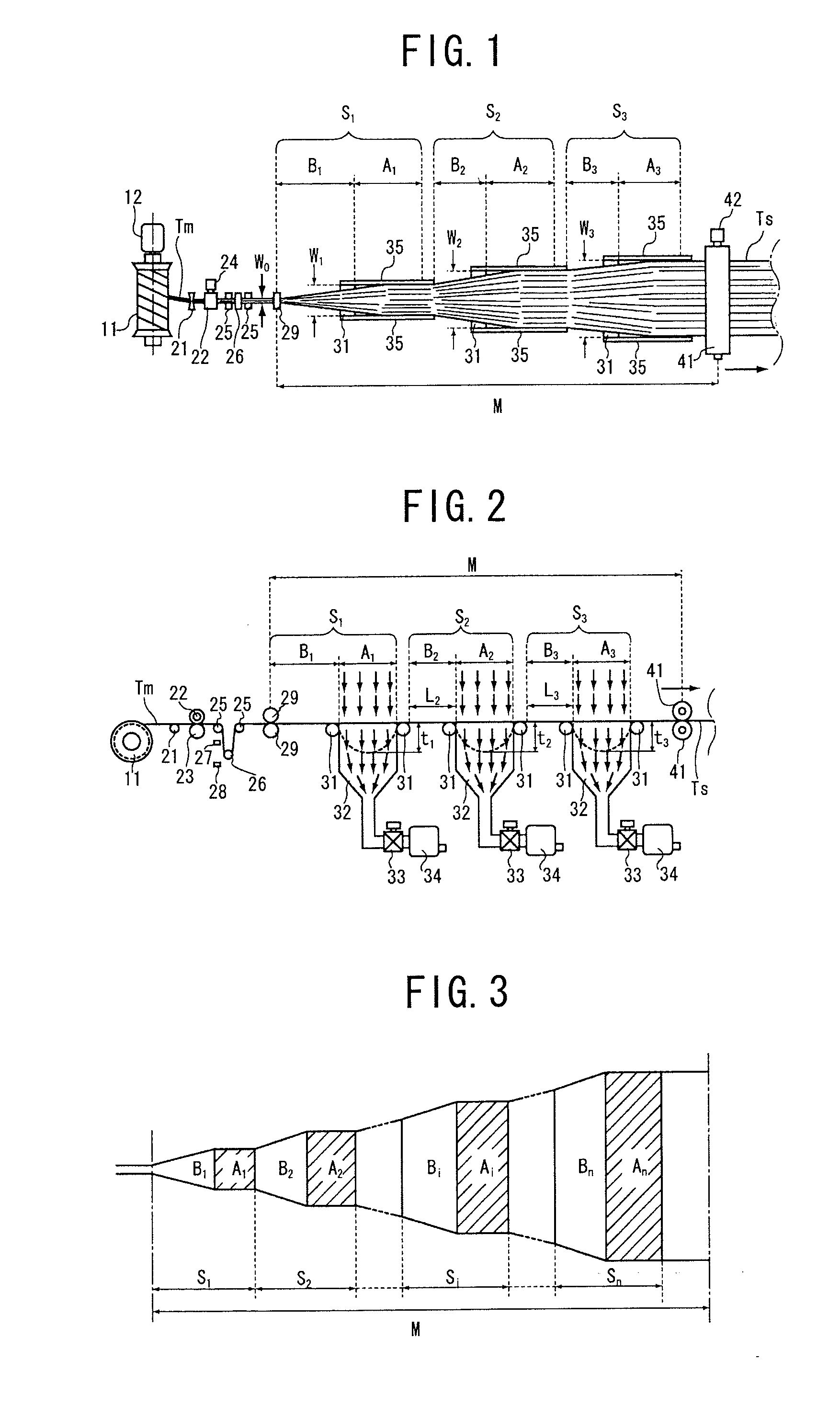
[0187]In the device illustrated in FIGS. 11 and 12, a device configuration in which two spread portions were arranged, the vertical vibration-giving mechanism was installed in the downstream-side spread portion, and the heating mechanism 61 illustrated in FIG. 14 was put into practice. As the fiber bundle, a carbon fiber (by Toray Industries Inc., Torayca T700SC-12K: fiber diameter of approximately 7 μm and the number of fibers of 12000) was used. The original width W0 of the fiber bundle was approximately 7 mm.

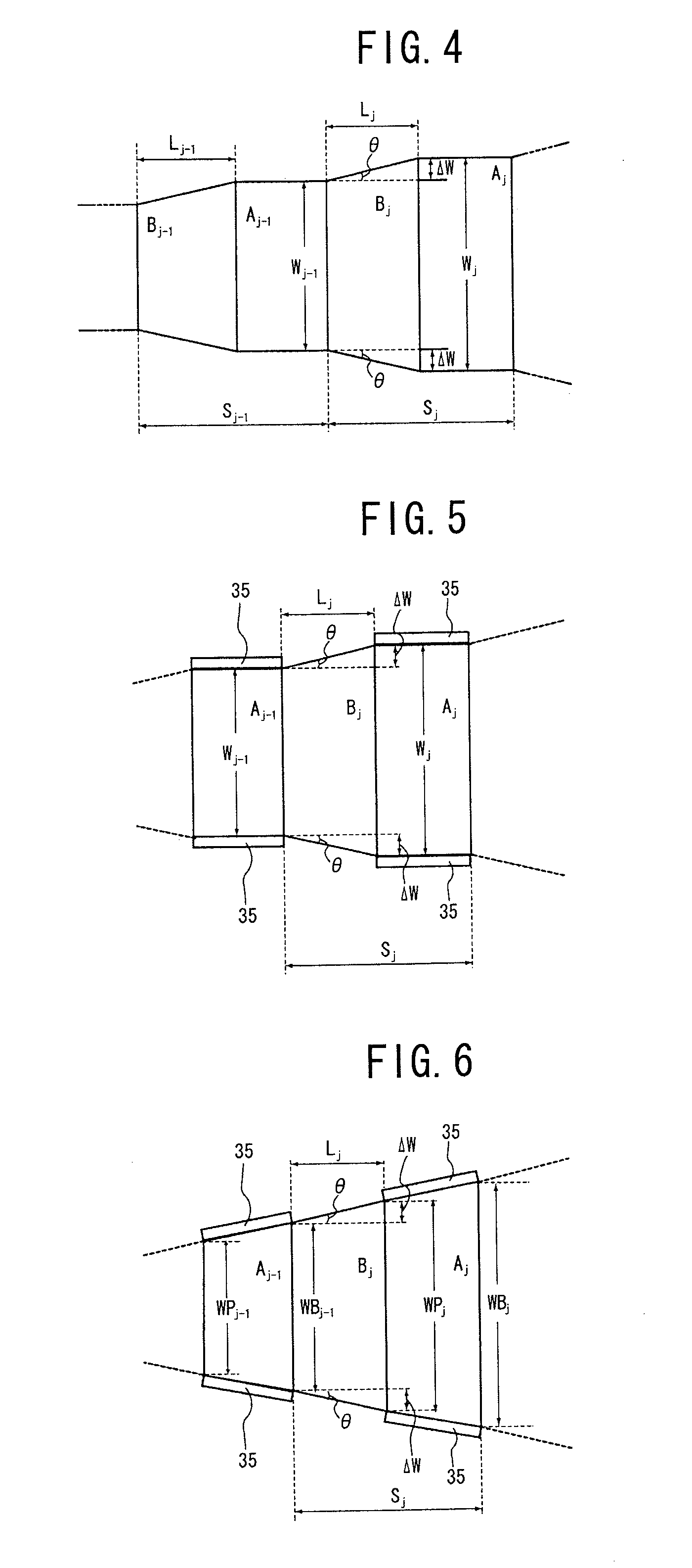
[0188]The spread width W1 of the fiber-spreading region Al was set to 16 mm, the spread width W2 of the fiber-spreading region A2 was set to 27 mm, the length L2 of the expansion region B2 in the feeding direction was set to 30 mm, and the expansion angle θ was set to approximately 10°. The length of each fiber-spreading region between the guide rolls was 20 mm, and the diameter of the guide roll was 6 mm, and the pearskin finish was applied to the surface. The diame...

example 2

[0192]In the device illustrated in FIGS. 11 and 12, a device configuration in which two spread portions were arranged, the vertical vibration-giving mechanism was installed in the downstream-side spread portion, and the heating mechanism 61 illustrated in FIG. 14 was put into practice. As the fiber bundle, a carbon fiber (by Mitsubishi Rayon Co., Ltd., PYROFIL TR50S-15K: fiber diameter of approximately 7 μm and the number of fibers of 15000) was used. The original width W0 of the fiber bundle was approximately 6 mm.

[0193]The spread width W1 of the fiber-spreading region A1 was set to 25 mm, the spread width W2 of the fiber-spreading region A2 was set to 48 mm, the length L2 of the expansion region B2 in the feeding direction was set to 30 mm, and the expansion angle θ was set to approximately 21°. The length of each fiber-spreading region between the guide rolls was 20 mm, and the diameter of the guide roll was 6 mm, and the pearskin finish was applied to the surface. The diameter o...

example 3

[0197]The same device configuration and the same carbon fiber bundle as in Example 2 were used.

[0198]The spread width W1 of the fiber-spreading region A1 and the spread width W2 of the fiber-spreading region A2 were set the same as those in Example 2. The length L2 of the expansion region B2 in the feeding direction was set to 20 mm, and the expansion angle θ was set to approximately 30°. The length of each fiber-spreading region between the guide rolls, the diameter of the guide roll and the surface treatment, the diameter of the bend ensuring roll and the surface treatment, and the position of the bend ensuring roll were set the same as those in Example 2.

[0199]The initial tension, given to the fiber bundle, the feeding speed of the fiber bundle, the flow velocity of the suction airflow in the spread region, the hot air temperature from the heating mechanism, the vibration rate of the vertical vibration-giving mechanism and the diameter of the pressing roll, the surface treatment ...


PUM

PropertyMeasurementUnit
Thicknessaaaaaaaaaa
Thicknessaaaaaaaaaa
Thicknessaaaaaaaaaa

Abstract

The present invention has an object to provide a fiber-spreading method which can form a thin spread fiber sheet having a large and uniform spread width by uniformly distributing fibers of a fiber bundle having an increased number of fibers. Since a set of regions Si each including a pair of a fiber-spreading region Ai and an expansion region Bi are arranged in a movable region M set so that the fibers of the fiber bundle can move in the width direction, the fiber-spreading region Ai moving the fibers in the width direction while bending the fibers by letting a fluid pass through the fiber bundle, thereby spreading the fiber bundle to a spread width Wi (i=1, . . . , n), and the expansion region Bi which is set on the upstream side in the feeding direction corresponding to the fiber-spreading region Ai and in which the width of the fiber bundle expands toward the end with movement of the fibers in the width direction in the fiber-spreading region Ai, by performing pre-spreading in which a movement phenomenon in the width direction caused by distribution of the fibers of the fiber bundle occurring in the fiber-spreading region Ai is made to act on the expansion region Bi on the upstream side, the fibers can be uniformly distributed in the fiber-spreading region Ai and the spread width can be expanded to a predetermined width so as to make the thickness uniform.

Description

TECHNICAL FIELD[0001]The present invention relates to a method for spreading fiber bundles by feeding a fiber bundle made of a large number of fibers in a fiber length direction and moving the fibers in a width direction while bending the fibers by letting a fluid pass through the fiber bundle, thereby spreading the fiber bundle, and relates to a spread fiber sheet obtained by spreading the fiber bundles, and a method for manufacturing a fiber-reinforced sheet in which a resin material is caused to adhere to or to impregnate the spread fiber sheet.BACKGROUND ART[0002]A fiber-reinforced composite material in which reinforced fibers such as a carbon fiber, a glass fiber, and an aramid fiber and a matrix resin such as an epoxy resin are combined has been developed, and regarding such reinforced fibers, by laminating thin spread fiber sheets aligned in one direction in multiple directions for use, reliable composite material moldings with high strength can be obtained. Also, in view of ...

Claims


Application Information

Patent Timeline
IPC IPC(8): B32B5/02B27N3/00D01D11/02
CPCC08J5/043D01D11/02D02J1/18Y10T428/268D04H3/04D04H3/12B29B15/12D04H3/002
Inventor KAWABE, KAZUMASA
Owner FUKUI PREFECTURE
Why Eureka
Try Eureka