Vehicle electrocatalyzer for recycling carbon dioxide to fuel hydrocarbons

a technology of electrocatalyzer and fuel hydrocarbon, which is applied in the direction of fuel cell, non-fuel substance addition to fuel, exhaust treatment, etc., can solve the problems of insufficient treatment of two aforementioned concerns and failure of devices to deal with carbon dioxide, so as to reduce the greenhouse effect and reduce the total fuel consumption of the vehicle

Inactive Publication Date: 2012-06-07
KING FAHD UNIVERSITY OF PETROLEUM AND MINERALS +1
View PDF5 Cites 28 Cited by
  • Summary
  • Abstract
  • Description
  • Claims
  • Application Information

AI Technical Summary

Benefits of technology

[0006]The vehicle electrocatalyzer for recycling carbon dioxide to fuel hydrocarbons includes a tubular member having a plurality of catalytic cells electrically connected in series and separated from one another by semipermeable membranes that allow the passage of fluids, but not solids. The electrocatalyzer can be attached in the vehicle's exhaust system, where hydrogen could be generated by the electrolysis of water. Metallic copper, iron, carbonaceous materials (such as activated carbon, carbon nano-materials, or graphite), metal oxides, or metal-supported catalysts may be used in each catalytic cell. A DC current connected across the cells is used to initiate reaction of the CO2 with hydrogen gas. The resulting hydrocarbons are recycled back to the vehicle engine and used as a makeup fuel. The electrocatalyzer will decrease the total fuel consumption in the vehicle and will be an environmentally friendly device acting to decrease the greenhouse effect, which is drastically affecting the global warming.

Problems solved by technology

These devices, however, fail to deal with carbon dioxide (CO2), a known greenhouse gas.
Thus, at least the two aforementioned concerns have not adequately been dealt with until now.

Method used


Image

  • Vehicle electrocatalyzer for recycling carbon dioxide to fuel hydrocarbons
  • Vehicle electrocatalyzer for recycling carbon dioxide to fuel hydrocarbons
  • Vehicle electrocatalyzer for recycling carbon dioxide to fuel hydrocarbons

Examples


Embodiment Construction

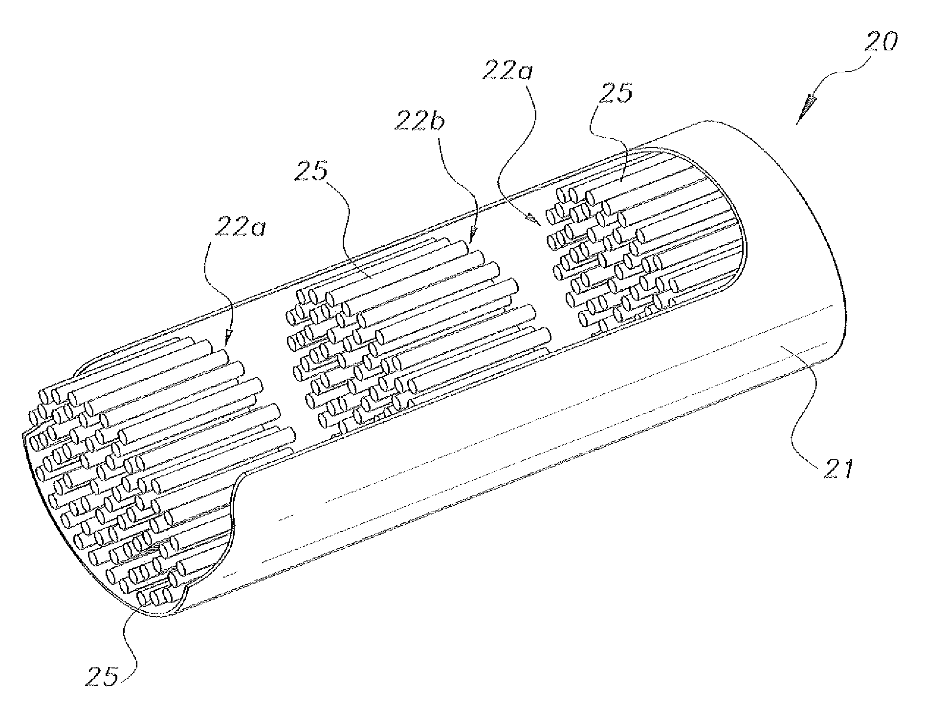
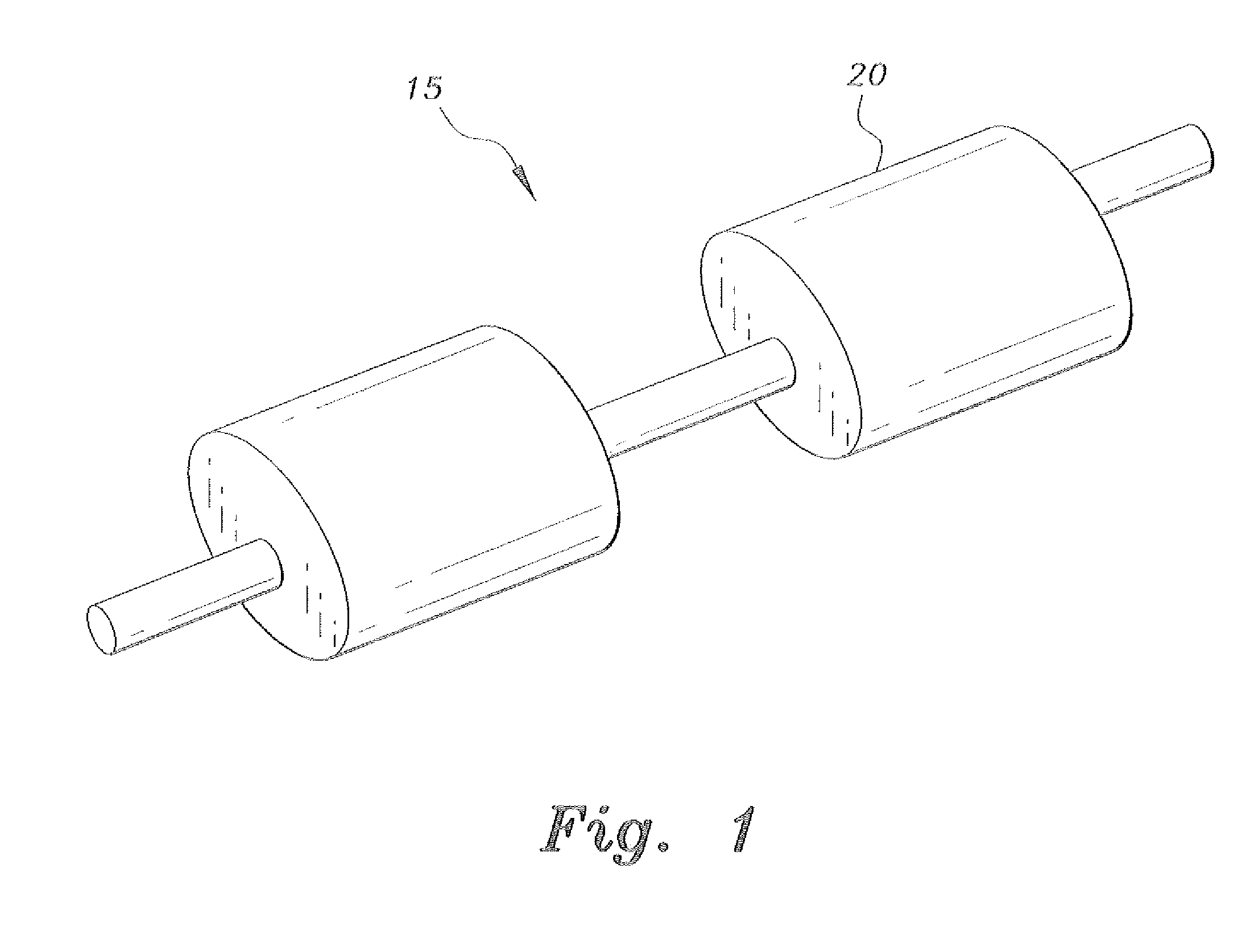
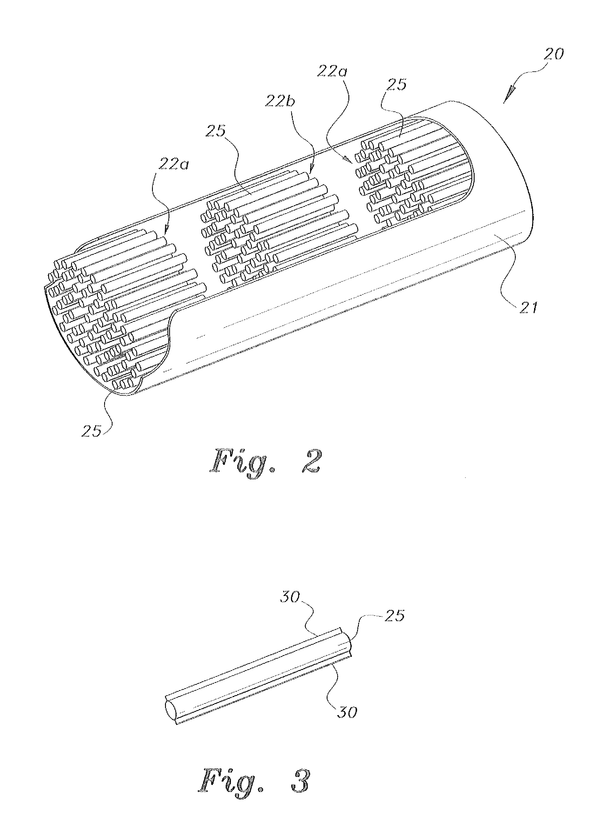
[0013]As shown in FIGS. 1-3, an exemplary vehicle electrocatalyzer 20 has a hollow outer shell 21 that houses a plurality of multistage, electrically conducting inner tubular electrocatalytic cell modules 22a (positive) and 22b (negative) connected in series and spaced at intervals in an alternating manner inside and along an axial center of the outer shell 21. The tubular modules 22a and 22b function as electrodes and are suspended in the outer shell 21 by a fluid disposed inside the outer shell 21. Each module 22a, 22b has a length of approximately 5-10 cm, and is then followed by an isolator from the other modules that are connected to the previous ones in series. Each inner tube 25 of the inner tubular modules 22a, 22b is coated with thin, elongate fin-like members 30 composed of nanoparticles. These cells will accommodate the catalyst like metallic copper, iron, carbonaceous material (such as activated carbon, carbon nanomaterial, or graphite), metal oxides, or metal-supported ...


PUM


Abstract

The vehicle electrocatalyzer for recycling carbon dioxide to fuel hydrocarbons includes a main tubular member having a plurality of tubular catalytic cells, electrically connected in series disposed inside and separated from one another by semipermeable membranes allowing the passage of fluids, but not solids. The electrocatalyzer can be attached in the exhaust system where hydrogen could be generated by the electrolysis of water. Metallic copper, iron, carbonaceous materials (such as activated carbon, carbon nanomaterials, or graphite), metal oxides, or metal-supported catalysts may be used in each catalytic cell. A DC current connected across the cells is used to initiate reaction of the carbon dioxide with hydrogen gas. The resulting hydrocarbons are recycled back to the vehicle engine and used as a makeup fuel.

Description

BACKGROUND OF THE INVENTION[0001]1. Field of the Invention[0002]The present invention relates to devices for controlling motor vehicle emissions, and particularly to a vehicle electrocatalyzer for recycling carbon dioxide to fuel hydrocarbons.[0003]2. Description of the Related Art[0004]Catalytic converters are devices used to reduce the toxicity of exhaust emissions from an internal combustion engine. Inside a catalytic converter, a catalyst stimulates a chemical reaction in which noxious byproducts of combustion (such as carbon monoxide, unburned hydrocarbons, and oxides of nitrogen) are converted to less-toxic or inert substances, such as carbon dioxide, hydrogen, nitrogen and oxygen. These devices, however, fail to deal with carbon dioxide (CO2), a known greenhouse gas. Moreover, with the ever rising gas prices there is a push to increase fuel economy. Thus, at least the two aforementioned concerns have not adequately been dealt with until now.[0005]Thus, a vehicle electrocataly...

Claims


Application Information

Patent Timeline
Patent Type & Authority Applications(United States)
IPC IPC(8): F01N3/10
CPCF01N3/04F01N3/0892F01N3/2006Y02T10/26F01N2610/04Y02T10/16F01N5/02Y02A50/20Y02T10/12
Inventor SHAWABKEH, REYAD AWWAD KHALAFABULKIBASH, ABDALLA MAHMOUDAL-SALEH, MUHAMMAD A.
Owner KING FAHD UNIVERSITY OF PETROLEUM AND MINERALS
Why Eureka
Try Eureka