Piezoelectric resonating device, manufacturing method thereof, piezoelectric resonator, and piezoelectric oscillator

a manufacturing method and piezoelectric technology, applied in the direction of piezoelectric/electrostrictive device details, device material selection, instruments, etc., can solve the problems of high-order vibration mode, unstable vibration mode, and uneven piezoelectric vibration substrate, etc., to reduce deviation, small size, and less unnecessary vibration

Inactive Publication Date: 2012-06-07
SEIKO EPSON CORP
View PDF5 Cites 20 Cited by
  • Summary
  • Abstract
  • Description
  • Claims
  • Application Information

AI Technical Summary

Benefits of technology

[0046]The resonating gyro apparatus includes the resonating gyro device, the IC component that excites the driving resonating arms of the resonating gyro device and detects and processes the detection resonating arms, and the package in which the resonating gyro device and the IC component are accommodated. Since the respective resonating arms are excited by flexural vibration, it is possible to greatly decrease the deviation from a predetermined frequency due to over-etching when forming the shape of the piezoelectric substrate by an etching method. Moreover, since the frequency adjustment slit are provided, it is possible to obtain a resonating gyro apparatus in which the frequency adjustment amount of the resonating gyro device is small, and which has a small size and little unnecessary vibration.

Problems solved by technology

However, when the piezoelectric resonator is configured in such a way, a high-order vibration mode is likely to occur, and the vibration mode tends to become unstable.
However, the shape of a piezoelectric vibration substrate is not identical to but is slightly different from the designed shape due to an unevenness in the concentration of an etching solution, temperature, etching time, and the like when forming the piezoelectric vibration substrate by photolithography and etching methods.
However, when a piezoelectric substrate for the resonating gyro device is formed by photolithography and etching methods, it is difficult to obtain a piezoelectric substrate for the resonating gyro device having the same shape as designed due to an unevenness in etching time or the like.
Thus, desired properties are not obtained.

Method used


Image

  • Piezoelectric resonating device, manufacturing method thereof, piezoelectric resonator, and piezoelectric oscillator
  • Piezoelectric resonating device, manufacturing method thereof, piezoelectric resonator, and piezoelectric oscillator
  • Piezoelectric resonating device, manufacturing method thereof, piezoelectric resonator, and piezoelectric oscillator

Examples


second embodiment

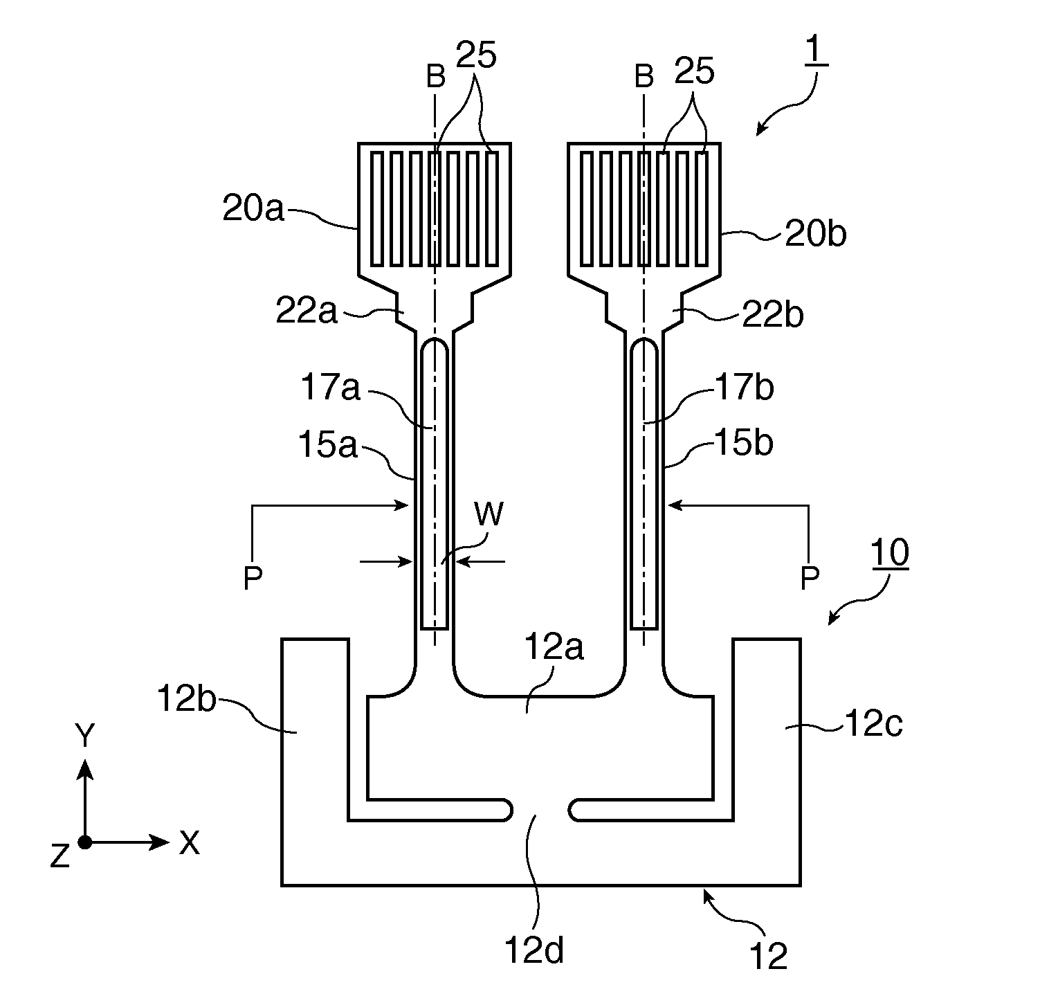
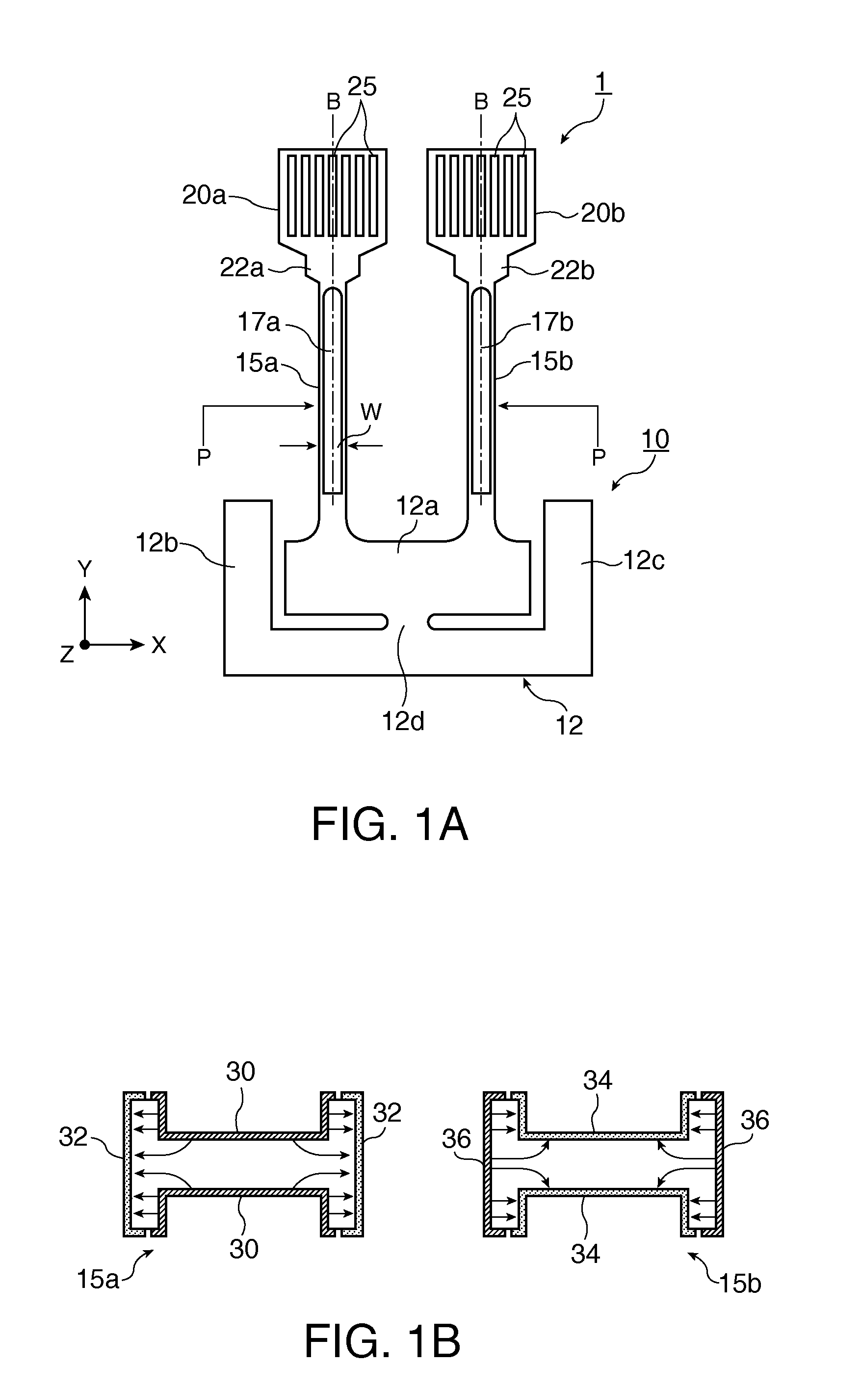
[0093]FIGS. 5A and 5B are views showing the configuration of a piezoelectric resonating device (tuning-fork type quartz crystal resonating device) 2 in which FIG. 5A is a plan view, and FIG. 5B is across-sectional view taken along the P-P line. A piezoelectric substrate 10 of the piezoelectric resonating device 2 includes a plurality of rod-shaped resonating arms 15a and 15b disposed in parallel and separated from each other, a base portion 12 that connects one set of end portions of the resonating arms 15a and 15b, groove portions 17a and 17b which are formed on each of a front surface and a rear surface along the center line of vibration B of each of the resonating arms 15a and 15b. Moreover, a plurality of frequency adjustment slits 25e penetrating through the front and rear surfaces of each of the resonating arms 15a and 15b so as to extend in a straight line form along the longitudinal direction of the resonating arms 15a and 15b are formed on the other set of end portions of ...

third embodiment

[0099]FIGS. 6A and 6B are views showing the configuration of a piezoelectric resonating device (torsional quartz crystal resonating device) 3 in which FIG. 6A is a plan view of a main part excluding weight portions, and FIG. 6B is a cross-sectional view taken along the line P-P. The weight portions of the piezoelectric resonating device (torsional quartz crystal resonating device) 3 have the same structure as the weight portions 20a and 20b shown in FIGS. 1A and 1B and the weight portions 20 shown in FIGS. 4A to 4D, and redundant description thereof will not be provided.

[0100]A quartz crystal substrate 40 of the torsional quartz crystal resonating device 3 includes a plurality of rod-shaped resonating arms 45a and 45b, a base portion 42 that connects one set of end portions of the resonating arms 45a and 45b, weight portions (the same as the weight portions shown in FIG. 1A or FIGS. 4A to 4D) which are formed on the other set of end portions of each of the resonating arms 45a and 4...

fourth embodiment

[0106]FIGS. 7A and 7B are plan views showing the configuration of a resonating gyro device 4 according to the A piezoelectric substrate 60 of the resonating gyro device 4 includes an approximately rectangular base portion 61, a pair of detection resonating arms 62a and 62b formed on the same straight line so as to protrude from the centers of two facing ends of the base portion 61; a pair of connecting arms 65a and 65b formed on the same straight line so as to protrude from the centers of another two facing ends of the base portion 61 in a direction orthogonal to the detection resonating arms 62a and 62b, respectively; a pair of driving resonating arms 67a and 67b and 70a and 70b protruding from the distal end portions of the respective connecting arms 65a and 65b in both directions orthogonal to the connecting arms 65a and 65b, respectively.

[0107]The respective detection resonating arms 62a and 62b and the respective driving resonating arms 67a, 67b, 70a, and 70b have weight porti...


PUM

PropertyMeasurementUnit
thicknessaaaaaaaaaa
thicknessaaaaaaaaaa
lengthaaaaaaaaaa

Abstract

A piezoelectric substrate includes rod-shaped resonating arms; a base portion that connects one set of end portions of the respective resonating arms; weight portions which are formed on the other end portions of the respective resonating arms and which have a width larger than that of the respective resonating arms; and groove portions which are formed on each of the front and rear surfaces along the center line of vibration of the respective resonating arms. The piezoelectric substrate also includes excitation electrodes which are formed on each of the front and rear surfaces of the respective resonating arms including the inner side of the respective groove portions. A plurality of frequency adjustment slits extending in a straight line form along the longitudinal direction of the respective resonating arms are formed on the respective weight portions so as to penetrate through the front and rear surfaces of the weight portions.

Description

BACKGROUND[0001]1. Technical Field[0002]The present invention relates to a piezoelectric resonating device, a method of manufacturing the piezoelectric resonating device, a piezoelectric resonator, and a piezoelectric oscillator.[0003]2. Related Art[0004]In the related art, piezoelectric resonators, for example, tuning-fork type quartz crystal resonators have been known. The tuning-fork type quartz crystal resonators are used, for example, in a reference frequency source of a timepiece or an angular velocity sensor of a piezoelectric gyro apparatus, and miniaturization of an electronic apparatus or the like having these resonators is progressing. In line with this, miniaturization of the piezoelectric resonator is also demanded.[0005]The vibration frequency of the tuning-fork type piezoelectric resonator is proportional to the width of a resonating arm and is inversely proportional to the square of the length thereof. In order to miniaturize the piezoelectric resonator, it is necess...

Claims


Application Information

Patent Timeline
Patent Type & Authority Applications(United States)
IPC IPC(8): G01P3/48H01L41/22H01L41/107H01L41/04H01L41/053G01C19/56G01C19/5621G01C19/5628H01L41/08H01L41/09H01L41/18H01L41/23H01L41/311H01L41/332H03B5/32H03H3/02H03H9/02H03H9/19H03H9/215
CPCH03H9/21Y10T29/42H03H9/215
Inventor YAMADA, AKINORI
Owner SEIKO EPSON CORP
Why Eureka
Try Eureka